2
Cryoablation: Mechanism of Actionand Devices
Though initially introduced in the 19th century, cryoablation entered mainstream clinical medicine in the mid-1960s.1 Because of technical limitations, however (i.e., large-bore probes to accommodate the large gas flow required and to facilitate adequate heat exchange), its applications were limited in the operative setting. In the last few years, as technology spawned the introduction of thinner cryoprobes (down to 14-gauge), image-guided, percutaneous cryoablations have carved out an ever-expanding niche. Currently, cryoablation is extensively used in the treatment of prostate cancer and renal cancer (either during open surgery or laparoscopically). Image-guided percutaneous cryoablation is mostly used for the treatment of small renal cancers and for the palliation of painful bone lesions. To a lesser extent, it is also used for the treatment of primary and secondary liver and chest neoplasms.
The technical goal of cryoablation is to reduce the temperature of the target tissue as well as an appropriate surrounding margin (equivalent to the surgical margin) to below lethal levels, without damaging vital nearby organs. For mammalian tissue, lethal temperature is below approximately −20° to −25°C (or −4° to −13°F). Cytotoxicity is mediated via various mechanisms, including ischemia, denaturing of protein structures, and the breakdown of cellular and intracellular membranes due to the formation of ice crystals. Some authors believe that the extracellular scaffolding structure is relatively preserved during cryoablation. This theoretically allows for the cellular repopulation of the tissue, which may explain why cryoablation is more forgiving, compared with radiofrequency ablation (RFA), in cases of nontarget ablation.
♦ The Physics of Cryoablation
The objective of cryoablation (kryo = “cold” in Greek; and ablatus = “to carry away” in Latin) is to reduce the temperature of the target tissue to below the lethal −20°C. This requires a continuous removal of energy from the entire target tissue. There are three ways that thermal energy may be transferred from one volume to another: (1) by conduction, the transfer of energy (or heat) from an object to a another at a lower temperature by virtue of physical conduct (direct molecular kinetic energy exchanges); (2) by convection, the transfer of energy (or heat) from an object to another at a lower temperature, with one of the objects being a flowing fluid (thus providing a continuously refreshed heat sink or heat source); and (3) by radiation, which removes radiant energy from all bodies above absolute zero temperature. No significant radiation losses are observed in our case; therefore, we can concentrate on conduction and convection (Fig. 2.1).
Conduction is a steady-state transfer because (in our case) it depends only on the temperature difference, which is relatively stable (i.e., tissue temperature [37°C] versus probe temperature [approximately −140°C]). On the other hand, convection depends on the flow rate of the blood through or adjacent to the volume of interest. Therefore, large-diameter arteries or very vascular tissues, to a lesser degree, will limit the extent of cryoablation. The reverse of this phenomenon (cooling of tissue by nearby flowing blood) has been termed “heat sink” in the case of thermal ablations (such as RFA or microwave ablation).
One advantage of cryoablation over RFA and microwave ablation is that the tissue energy transfer characteristics do not appreciably change with temperature. In contrast, in the case of RFA, tissue desiccates at high temperature and no further transfer of energy is possible. Irrespective of the tissue temperature, further temperature reduction is always theoretically possible with cryoablation.
The removal of energy (cooling) from the tissue surrounding the cryoprobe is effected by the Joule-Thomson law.2 During gas expansion two opposing mechanisms take effect. First, as intermolecular distances increase with cooling, the potential energy stored between molecules increases. Because total energy must be conserved, this translates into lower molecular kinetic energy and therefore lower temperature. Second, as intermolecular distance increases, however, fewer molecular collisions result in a relative decrease in potential energy stored between molecules. Again, because total energy must be conserved, this results in greater molecular kinetic energy and therefore greater temperature. Which of the two competing mechanisms dominates depends on the so-called inversion temperature of the gas, which is an intrinsic property. For argon, nitrogen, or oxygen, the inversion temperature factor is greater than room (or ambient) temperature and the first mechanism dominates. For helium and hydrogen, the inversion temperature is less than room temperature. Therefore, expansion of compressed argon, nitrogen, or oxygen causes cooling, whereas expansion of helium or hydrogen causes warming.
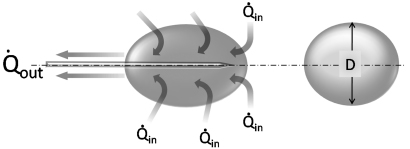
Fig. 2.1 Schematic of heat transfer during cryoablation. The dynamics of cryoablation are the result of two competing processes: the heat transfer rate into (Qin) and the heat transfer rate out of (Qout) the volume of interest (ice ball). The size or diameter (D) of the ice ball depends on the difference between the two transfer rates. During the initial portion of cryoablation, Qout is greater than Qin and the ice ball grows continuously. As it does, however, so does its surface area, which results in a concomitant increase in Qin (as more normal-temperature tissue comes in contact with the expanding ice ball). Since Qout is stable and dependent only on the flow rate of the expanding gas through the probe, at some point Qout will be equal to Qin and the ice ball will stop growing. This is the steady-state portion of the cryoablation, and it is the ice-ball size at this point that manufacturers publicize. Qin, the heat transfer rate into the ice ball, is the sum of conductive and convective energy transfers from adjacent tissues. The former predominates and depends on the surface area of the ice ball, whereas the latter depends on the flow rate of nearby large blood vessels.
The gas is supplied by a gas tank to the probe via a pressure regulator (Fig. 2.2). Gas expansion occurs within the dual chambered cryoprobe (Fig. 2.3). The gas, once it expands, cools, absorbs thermal energy from the surrounding tissues, and is siphoned back through the tubing and eventually released into the atmosphere. The diameter of the “ice ball” depends on the rate of energy transfer, which in turn depends on the flow rate of the cooling gas through the probe. The length of the ice ball mostly depends on the uninsulated length of the probe (Fig. 2.4).
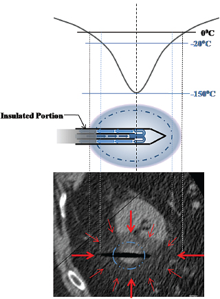
It is worth repeating that the lethal temperature for mammalian tissue is −20°C or colder. This does not correspond to the visible margin of the ice ball as seen under computed tomography (CT), ultrasound (US), or magnetic resonance (MR) guidance, which is at 0°C. Studies have shown that the −20°C isotherm is at least 5 mm inside the 0°C isotherm.3
♦ Ablation Systems
There are currently two U.S. Food and Drug Administration– approved cryoablation systems available in the United States, which at the time of writing of this chapter were in advanced merger discussions. Both systems, Endocare and Galil, make use of the above basic physical properties of the gases, and both utilize argon for freezing and helium for thawing. This may change in the near future as technologic advancements may allow the reintroduction of a single gas cooling-thawing system using nitrogen.
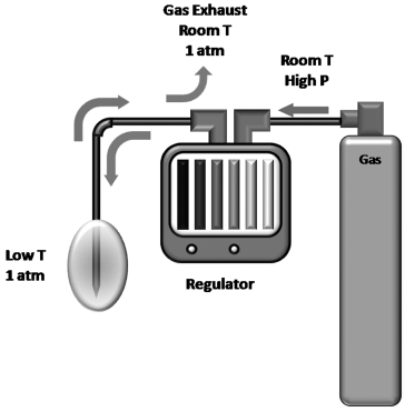
Fig. 2.2 Diagram of the gas supply during cryoablation. The gas is stored in a high-pressure cylinder. For ultrahigh purity medical gases, the pressure is usually 6000 psi. At this pressure one argon tank provides enough gas for approximately 8 to 10 single-probe cryoablations. A full helium tank will suffice for 10 to 15 single-probe thawings. The latter is not absolutely necessary. Active thawing reduces the waiting time to 2 to 4 minutes from that of 6 to 12 minutes for passive thawing. The gas tanks are connected to the regulator via high-pressure cables. The operator uses the regulator to start or stop cryoablation once the probes are in the proper position. Rarely, when the operator needs to limit the size of the ice ball, the regulator can decrease the rate of gas flow to the probe, which decreases the rate of heat removal from the target tissue and consequently the final size of the ice ball. The pressurized gas is transferred to the probe, where it is allowed to decompress to 1 atmosphere within the probe. The Joule-Thomson effect dictates that, for certain gases, including nitrogen, argon, and oxygen, this rapid decompression results in cooling of the gas. The cooled gas removes energy (Qout) from the tissue around the probe and circulates back toward the regulator. Finally the gas is exhausted into the room (inert gas) at 1 atmosphere and at room temperature.
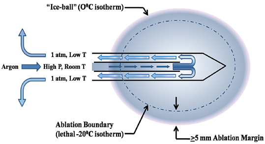
Fig. 2.3 Schematic of the cryoprobe and its function. The cooling gas (argon in this case) is carried to the probe via a high-pressure cable at room temperature and under high pressure. Near the tip of the two-chambered probe, the gas is released into the probe, where its pressure equilibrates with ambient pressure (approximately 1 atmosphere). This rapid decompression results in the supercooling of the gas (Joule-Thomson effect) and gradually of the probe and the surrounding tissues, forming the ice ball. The margin of the ice ball as noted on CT or US represents the 0°C isotherm. This temperature is not lethal to mammalian tissue, and therefore the ice ball should not be thought of as the ablation region. Rather, at least a 5-mm ablation margin is required to reach the lethal −20°C and ensure tissue death.
Endocare
With the Endocare (Irvine, CA) system, there are four cryoprobe types available for use, differing in the shape and size of the generated ice ball (Fig. 2.5). Probe selection depends on the size and shape of the target lesion. For example, a 1-cm lesion in a difficult-to-access location is best approached with the Perc-15 probe. In general the Perc-24 is the workhorse probe for this system, as it yields the largest ablation zone. The respective isotherms for each probe are graphically shown in Fig. 2.6. Endocare also provides a percutaneously inserted temperature sensor (Fig. 2.5). This may be useful in rare instances when the temperature near a nontarget organ needs to be monitored.
The Endocare regulator is shown in Fig. 2.7. The regulator is composed of gas inlet hookups (argon and helium in); gas outlet hookups (argon, helium out); the internal regulator design; the control panel; and the screen, which can display the readings from up to eight cryoprobes and eight temperature sensors.
Galil
The Galil (Yokneam, Israel) Seednet and Presice regulators (which have the capacity to utilize and monitor up to five cryoprobes simultaneously) are shown in Fig. 2.8. The design of the cryoprobes differs slightly from that of Endocare’s in that they are a thinner (17-gauge) (Fig. 2.9). Four cryoprobes are available—the IceBulb, the IceRod, the IceSphere, and the IceSeed—which differ in the shape and size of the ice ball generated. The Galil cryoprobe isotherms are shown in Fig. 2.10 and sample ice balls are depicted in Fig. 2.11. As with Endocare, the choice of the number and type of cryoprobes depends on the size and shape of the target lesion. The operator must “sculpt” an ice ball by placing the appropriate number and type of probes at such angles with respect to each other so that the resulting ice ball covers the entire target lesion as well as a 5-mm margin, at least. For detailed temperature monitoring, Galil provides specific temperature sensors (Fig. 2.12), as the cryoprobes themselves do not have incorporated thermocouples. These sensors can be placed between the target lesion and nontarget organ to monitor the temperature near the nontarget organ, or in or near the target lesion to monitor the effectiveness of cryoablation. They are capable of providing real-time temperature measurements at multiple points, that is, at 5, 15, 25, and 35 mm from the tip.
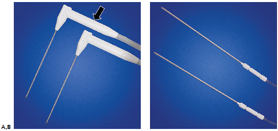
Fig. 2.5 (A) The Endocare cryoprobes. The right-angle design facilitates probe insertion within the confines of a CT gantry and is especially useful for obese patients. Because of design limitations, the internal thermocouple is contained within the distal shaft of the cryo-probe (arrow). As a result, the actual temperature at the tip of the probe is approximately 10° to 12°C colder than the display reading. It is necessary to allow the probe to thaw to above +10°C; otherwise, the still frozen tip sticks to the tissue and makes insertion or removal difficult. (B) Temperature sensors can be used if necessary to monitor the temperature near a critical nontarget structure. They measure a single point temperature at the tip of the sensor.
Ablation Protocols
The ablation protocols have been developed mostly based on empirical observations. Deviations from the protocols should be discouraged unless patient safety is compromised in not doing so. For example, an expanding ice ball that threatens to invade the nearby bowel may precipitate either early termination or reduction in the power of the closest probe, if more than one is used. Cell death is precipitated not only by the low temperatures but also by the effects of rapid cooling, thawing, and recooling, which result in ice crystal formation and cell membrane disruptions. Cooling for longer than the protocol recommends does not appreciably increase the size of the ice ball as the system approaches a plateau along the heat exchange curve as explained in the physics section above. Similarly, applying more than the recommended ablation cycles does not appreciably increase the cytotoxic effect of the ice ball.
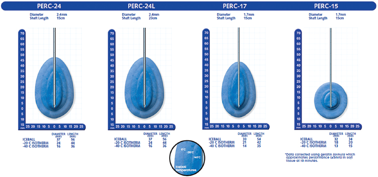
Fig. 2.6 Isotherms for the Endocare probes. The margin of the ice ball as seen on CT or US represents the 0°C isotherm. This can be used as a safety factor to minimize the risk of nontarget ablation; however, it is not lethal. The lethal isotherm is the one at −20°C, and it varies from probe to probe. For example, the lethal isotherm for the Perc-24 is an oval/teardrop-shaped volume with a 44-mm long diameter and a 24-mm short diameter. The thicker the probe, the faster the cooling gas can circulate, and thus the larger the effective isotherm. A lesion with a diameter of 1.5 cm theoretically can be ablated using only one Perc-24 cryoprobe. In reality, however, this is unlikely, because such an outcome presupposes the insertion of the single probe perfectly within the center of perfectly spherical mass. It is prudent to be liberal with the use of cryoprobes and ensure adequate target mass and margin ablation, rather than risk having to re-treat the patient in the near future.
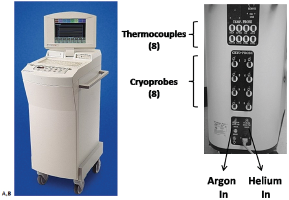
Fig. 2.7 The gas regulator from Endocare allows the use of up to eight cryoprobes simultaneously. (A) The front view shows the screen, which displays the time, temperature, and flow (0– 100%) for each one of up to eight cryoprobes simultaneously. The percent flow is set to 100% for all probes unless one is close to a nontarget organ, and the operator wishes to limit the extension of the ice ball in that direction. (B) The rear view of the regulator shows the various ports, including eight for cryoprobes, eight for additional thermocouples (if necessary), as well as the gas inlet.
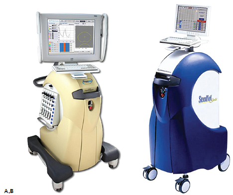
Fig. 2.8 Galil regulators. The two regulators available for use with Galil cryoprobes are the Presice (A) and the Seed-net (B). The former allows for the simultaneous use and monitoring of up to five cryoprobes. Both the Endocare and Galil regulators use argon for freezing and helium for thawing.
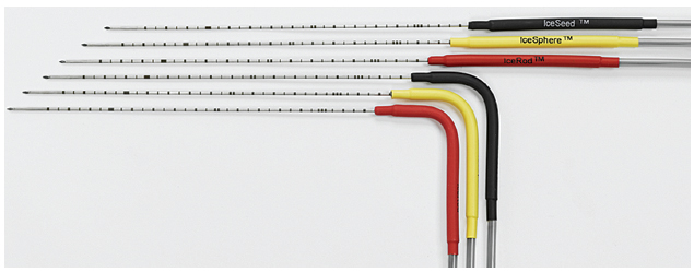
Fig. 2.9 There are four types of cryoprobes available for use with the Galil regulator: the IceBulb, the IceRod, the IceSphere, and the IceSeed. They differ in the shape and size of the generated ice ball, and they come with straight and right-angle shafts. Although probes with straight shafts are generally easier to use during open or laparoscopic cryoablations and during percutaneous prostate cryoablations, the angled probes are more user friendly in the confined space of the CT gantry, especially for obese patients. The Galil cryoprobes are 17-gauge, slightly thinner than the most commonly used Perc-24 Endocare cryoprobe; however, they do not have an embedded thermocouple. If temperature monitoring is necessary, a temperature sensor must be placed.
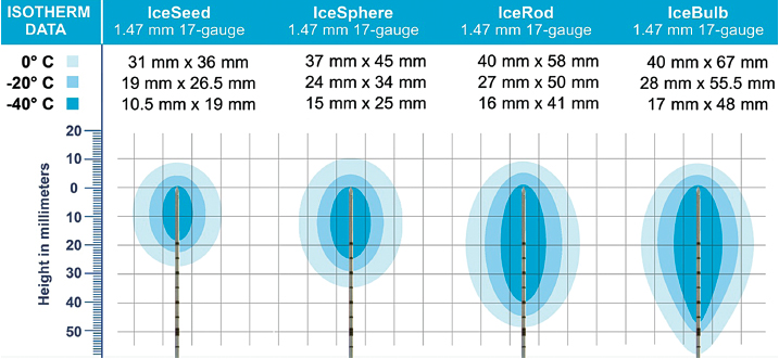
Fig. 2.10 The isotherms of the four Galil cryoprobes. As with the Endocare probes, the margin of the visible ice ball on CT, US, or MR imaging delineates the 0°C isotherm. The lethal −20°C isotherm is at least 5 mm deep to the 0°C isotherm.
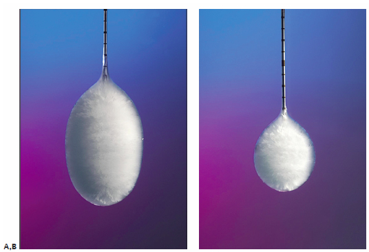
Fig. 2.11 The two commonly used Galil cryoprobes are the IceRod (A) and IceSphere (B). The IceRod generates a near cylindrical ice ball (compared with the teardrop-shaped ice ball generated by the Endocare Perc24 probe), with a long diameter of 58 mm and a short diameter of 40 mm. Its corresponding lethal measurements are 50 mm by 27 mm. The IceSphere, despite its name, generates an ice ball with a long diameter of 45 mm and a short diameter of 37 mm. Its corresponding lethal measurements are 34 mm by 24 mm.
Endocare Equipment Setup
Step 1: Connect gas tanks to regulator via high-pressure tubing.
Step 2: Turn on the regulator.
Step 3: Open the gas tank valves.
Step 4: Connect the cryoprobe(s) to the regulator. Connect both the gas flow tubing and the integrated thermocouple cable for each cryoprobe.
Step 5: With the cryoprobe immersed in saline, press “freeze” for 2 to 3 seconds and ensure that the probe is working and that there is no gas leak from it.
Step 6: Thaw the probes to above 10°C.
Step 7: Insert the probes and perform the ablation (see protocol below).
Step 8: Thaw to above 10°C and remove the probes.
Step 9: Record the residual gas tank pressure.
Step 10: Turn off the gas tank valves.
Step 11: Bleed the regulator (follow the on-screen instructions after pressing shutdown).
Step 12: Disconnect and discard the probes.
Step 13: Turn off the regulator.
Endocare Protocol
The protocol is set irrespective of the location, type, and number of probes or the location, size or kind, of tumor. It consists of a 10-minute freeze, followed by an 8-minute thaw and another 10-minute freeze, of all probes simultaneously. Some authors support the notion that the thaw cycle should be active (helium circulates) and not passive (no gas circulation) because faster thawing may improve the cytotoxic effect of cryoablation. In theory this is correct; however, prior to the second freeze cycle the location of the probes must be verified as they may have moved during active thawing.
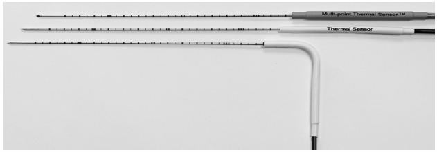
Fig. 2.12 Temperature sensors are available for use with the Galil cryoablation system. The multipoint thermal sensor provides real-time temperature readings at 5 mm, 15 mm, 25 mm, and 35 mm from the tip. It can be used either to ensure safety by monitoring the temperature near a nontarget organ, or to improve efficacy by placing it through or alongside the target mass.
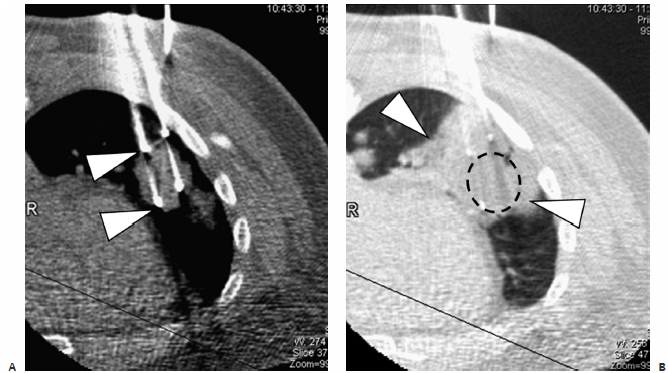
Fig. 2.13 (A) An axial CT image during cryoprobe insertion in a patient with lung cancer. The “active” part of the cryoprobe is discernible as it is slightly less radiodense than the rest of the probe (arrowheads). The ablation zone does not extend more than 1 to 2 mm distal to the tips of the cryoprobes; therefore, their tips should be placed at the distal margin of the tumor. Cryoablation of lung lesions has an increased risk of hemorrhage compared with RFA, as the former does not coagulate damaged vessels. (B) Axial CT image at the end of the ablation shows an alveolar hematoma (arrowheads) surrounding and obscuring the target mass (dashed circle). It should be remembered that many patients with primary lung cancer referred for ablation suffer from significant chronic obstructive pulmonary disease, which for many is the reason they cannot have surgery in the first place. A significant alveolar hemorrhage can have serious clinical consequences in these patients.
Galil Equipment Setup
Step 1: Connect the gas tanks to the appropriate inlet valve on the back of the Presice regulator. Make sure the safety clip (one for each line) is also attached.
Step 2: Open the gas tank valves.
Step 3: Power up the regulator.
Step 4: After matching the digital pressure readout, insert the GoldCard and activate the “Start Procedure” icon.
Step 5: Follow instructions ensuring the displayed information corresponds to the procedure details:
A: If the probe and the procedure are correct, activate “Continue.”
B: If the thaw setting is correct activate “OK,” otherwise move the switch on the back 180°.
Step 6: Connect the probe.
Step 7: Test the probe in sterile saline or water, as above.
Step 8: Perform the ablation.
Step 9: Thaw to above +10°C and remove probe(s).
Step 10: Record the residual gas tank pressure.
Step 11: Turn off the gas tank valves.
Step 12: Bleed the Presice regulator.
Step 13: Disconnect and discard the probe(s).
Step 14: Turn off the regulator.
Galil Protocol
As in the case of the Endocare, the protocol is conserved. Deviations from the ablation protocol are only necessary to ensure safety. If, for example, the ice ball reaches a nontarget organ and no other thermoprotective maneuver is available, then the ablation time can be shortened. In the case of the Galil, the protocol consists of a 10-minute freeze, followed by a 5-minute thaw, and finally a 10-minute refreeze.
♦ Clinical Practice
Cryoablation theoretically can be used in any part of the body; however, its specific risks and benefits must be weighed against those of other ablation modalities. Lung cryoablation is possible and occasionally necessary (Fig. 2.13); however, one has to contend with a slightly higher risk of pulmonary hemorrhage compared with doing RFA. This can be clinically significant in patients with severe chronic obstructive pulmonary disease, who represent a good portion of the patients with primary lung cancer referred for ablation. In general, cryoablation for peripheral, pleura-based lesions is safer than for central ones. In addition, cryoablation for pleura-based lesions is essentially painless, in contrast to RFA. Primary and secondary liver cancer (Fig. 2.14) can be treated with cryoablation with probably similar efficacy and safety to that of RFA, though there is vastly more published data on the latter. The efficacy of cryoablation is affected by nearby large vessels, a phenomenon whose RFA counterpart is termed “heat-sink” effect. Blood vessels larger than 3 mm in diameter are known to affect the geometry of the ice ball. In such cases, additional probes, or even balloon occlusion of a hepatic vein (if this is the culprit), may be necessary. The most commonly treated tumor with cryoablation is renal cell carcinoma (Fig. 2.15), and it is also the one with the most published efficacy and safety data. The use of cryoablation for metastatic disease is not common, and its use should be limited to three indications: (1) in cases where tumor cytore-duction has been shown to improve survival (i.e., oligometastatic colon, breast, or renal cancer); (2) for the palliation of painful metastatic foci (Figs. 2.16, 2.17, 2.18, 2.19, and 2.20); or (3) to treat a metastasis whose further growth is expected to result in significant symptoms.
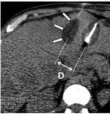
Fig. 2.14 An axial CT image during cryoablation of a large liver lesion. This cryoablation was performed as part of an experimental protocol during which only part of the mass is targeted, which explains why the cryoprobes were placed far apart. The result is the formation of two distinct ice balls (arrows) that do not coalesce. When more than one cryoprobe is used, the distance (D) between them should be less than 2 cm to ensure their ablation zones coalesce and that no viable tumor is left between them. Additionally, to maximize the size of the resulting ice ball, the cryoprobes should be placed as parallel to each other as possible.
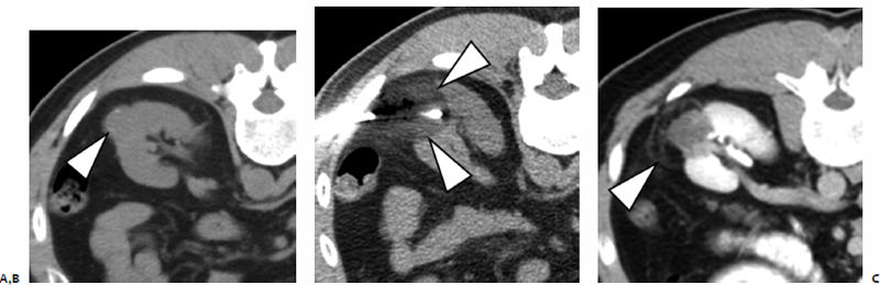
Fig. 2.15 (A) An axial CT image shows an exophytic left renal mass (arrowhead). (B) During cryoablation, the probe(s) are placed so that the ice ball (arrowheads) covers the mass and a >5-mm margin. (C) On the 3-month contrast-enhanced CT, the mass appears completely devascularized and the ablation zone in the perinephric fat is demarcated by a hypervascular rim (arrowhead).
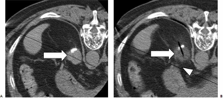
Fig. 2.16 (A) An axial CT image in a hepatocellular carcinoma patient with a single metastatic focus to the left adrenal (arrow). (B) During cryoablation, the entire mass (arrow) demonstrates lowered Hounsfield units its density decreases during freezing. The ice ball is difficult to visualize in fatty regions because its CT density is very close to that of fat. The periadrenal fat becomes “fuzzy,” indicating extension of the ice ball around the adrenal mass. Note the proximity of the ice ball to the stomach (arrowhead), which was a concern in this case. The edge of the ice ball demarcates the 0°C isotherm, which is not lethal.
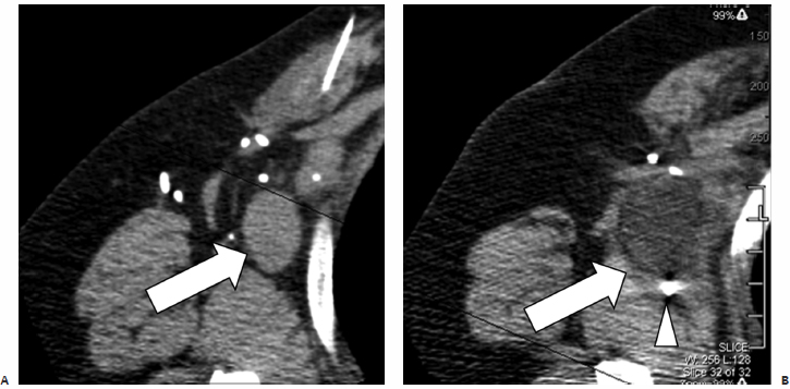
Fig. 2.17 (A) An axial CT image in a patient with metastatic breast cancer. Because the patient failed all standard treatment options, she was placed on an experimental cryotherapy protocol that involved single-lesion cryoablation followed by chemotherapy. During this treatment, a single large right axillary lymph node (arrow) was targeted. (B) An intraprocedural axial CT image shows the entire mass, demonstrating lowered Hounsfield units (arrow), compatible with freezing. The tip of the cryoprobe (arrowhead) is seen past the distal margin of the mass to ensure adequate ablation, as the ablation zone does not extend more than 1 to 2 mm beyond the tip.
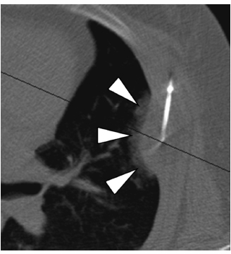
Fig. 2.18 An axial CT image during cryoablation of a painful left rib metastasis from colon cancer. The probe is placed along the long diameter of the lesion to improve coverage. Note the ice crystals forming in the pulmonary parenchyma (arrowheads), demarcating the margin of the cryoablation.
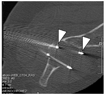
Fig. 2.19 An axial CT image during cryoablation of a painful renal cancer metastasis to the left iliac wing. The active portion of the cryoprobes is less dense than the rest of the probe (arrowheads). For palliation of destructive bone lesions, the operator must effectively target the involved periosteum, as it most likely is the source of the patient’s pain. The cryoablation protocol is conserved irrespective of the number of probes, cancer type, location, or objective, and consists of a 10-minute freeze, an 8-minute thaw (for Endocare; a 5-minute thaw for Galil), and a 10-minute refreeze.
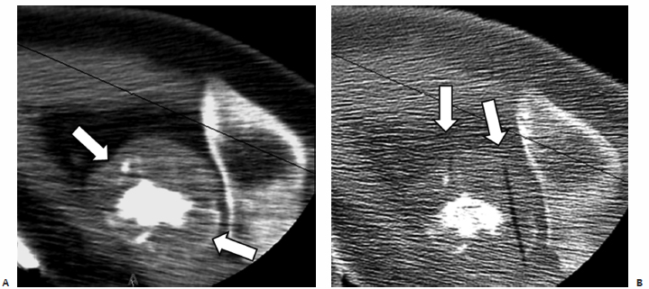
Fig. 2.20 (A) An axial CT image shows a destructive bone lesion involving the right humeral head and elevating the periosteum (arrows). (B) An intraprocedural CT during cryoablation shows the ghosts of two removed cryoprobes (arrows; out of a total of four used) targeting the involved periosteum.
- The lethal temperature is below −20°C.
- The visible ice-ball margin on CT demarcates the 0°C isotherm, which is not lethal. At least a 5-mm cryoablation margin beyond the target is thought necessary to ensure target ablation.
- An expanding gas cools if its inversion temperature is greater than the ambient temperature and warms if its inversion temperature is lower than the ambient temperature. This is termed the Joule-Thomson law or effect. This is why some gases cool (e.g., argon), whereas others warm (e.g., helium) on expansion.
- “Cryoshock” refers to cardiopulmonary collapse after a seemingly uneventful cryoablation. It is a diagnosis of exclusion, and the risk increases with increasing patient age, increasing size of ice ball, and preexisting cardiac or pulmonary disease. The risk is mitigated by staging the procedure and avoiding large-diameter ice balls.
- There is no advantage or disadvantage in using Endocare over Galil or vice versa. Therefore, the operator’s experience is the defining factor for safety and efficacy.
- It is better to err on the side of using more cryoprobes than to have to re-treat a residual tumor. Two probes placed at the margins of the target mass are far better than one probe going right through the mass’s center, even if the single probe’s ice ball theoretically covers the mass.


