1
Radiofrequency Ablation:Mechanism of Action and Devices
The application of radiofrequency (RF) energy and its thermal effects on tissue were described as early as 1891 by d’Arsonval, when RF waves that passed through tissue were observed to cause an increase in local tissue temperature. RF energy became incorporated into practical medicine via the invention of the Bovie knife used for both cauterization and cutting tissue by varying the RF current. A pulsed current caused cauterization of tissue, whereas a more continuous current caused cutting of tissue. The first-generation Bovie knife was a crude monopolar RF electrode with surface adhesive skin pads closing off the circuit. Use of RF application in thermal ablation was first reported by Rossi and by McGahan et al independently in 1992 for liver tumor ablation.
Since the early RF description, over 100,000 estimated liver RF ablation (RFA) procedures have been performed worldwide. The interest in percutaneous tumor ablation has considerably evolved with introduction of several other thermal modalities, including microwave, cryoablation, high-intensity ultrasound, irreversible electroporation, and interstitial laser.1 The evidence thus far suggests, however, that RFA should remain the prototypical ablation device, particularly for lesions <3 cm, and should still be the cornerstone of any ablation practice.2,3 It is the most frequently used ablative technique, and it has the longest track record.4 Familiarity with the RFA mechanism of action, clinical rationale, and techniques remains critical for the success of an ablation practice.5
♦ Physics and Principles
Radiofrequency refers to the part of the electromagnetic (EM) spectrum bounded by the frequencies of 3 Hz and 300 GHz (Fig. 1.1). EM radiation includes (in addition to radio waves) infrared radiation, the visible spectrum, ultraviolet radiation, x-rays, and γ-rays, in increasing frequency.
Even though all EM radiation subtypes have the same basic physical properties, their interactions with matter can be very different depending on their frequency and the type of matter. RF waves, as applied in medicine, cause thermal ablation of a defined volume of tissue. The RFA probe acts as the cathode of an electrical circuit that is closed by the application of dispersing pads on the patient’s thighs (Fig. 1.2). Because of the small cross-sectional area of the probe tip, there is a very high energy flux around it. On the other hand, the large cross-sectional area of the grounding pads disperses the energy, minimizing the energy flux. As a result, tissue damage is limited to the part of the circuit that surrounds the probe tip.3
RF ablation results in coagulative necrosis of tissue at high temperatures. The dipole molecules (mostly water) adjacent to the tip of the RF electrode attempt to remain aligned in the direction of current and are forced to vibrate as a rapidly alternating current is applied. Molecules farther away from the probe are set into motion by other vibrating molecules near them. The frictional energy losses between adjacent molecules result in local energy deposition and temperature increase. As one moves away from the source (probe), energy deposition and thus temperature both drop (Fig. 1.3). The RF electrode itself is not the source of heat and is not hot to the touch. It generates an alternating EM field that sets adjacent molecules into motion and intense agitation. The molecules immediately adjacent to the probe are the source of the heat, which is transmitted farther by tissue conductivity.
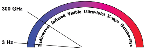
Fig. 1.1 The electromagnetic (EM) spectrum is modeled as a continuous frequency spectrum of vibrating massless energy quanta. The EM radiation is composed of both an electric and a magnetic field oriented at 90 degrees to each other. The EM radiation whose frequency is between 3 Hz and 300 GHz is defined as radiowaves.
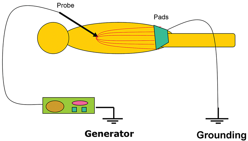
Fig. 1.2 The radiofrequency ablation circuit. The probe acts as the cathode and the pads as the anode. The patient is actually part of the circuit, and tissue conductivity is important in achieving adequate ablation zone.
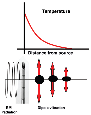
Fig. 1.3 The radiofrequency probe itself is not the source of heat. It generates an alternating electromagnetic field that sets adjacent molecules into motion. The molecules immediately adjacent to the probe are the source of the heat, which is transmitted farther by tissue conductivity.
One of the limitations of RFA is that it is heavily dependent on good electrical and thermal tissue conductivity for effective ablation.3 If one pushes the generator’s power too high too quickly, the tissue around the probe becomes desiccated (charred). The desiccated tissue acts as an insulating “sleeve” around the probe, which limits the transmission of further electrical or thermal energy (Fig. 1.4) and limits any further extension of desired tissue destruction. It is instructive to note that time is just as crucial in achieving a large ablation zone as the maximum temperature reached. Figure 1.5 demonstrates the approximate time needed for tissue death at various temperatures. Mammalian tissue is very sensitive to temperature changes. At 55°C, for example, tissue death results within 2 seconds. At 100°C, death is instantaneous as evaporation occurs. Microbubbles are produced and represent gases, primarily nitrogen, that are released from the cells. This, however, is not desired in RFA because of the insulating effect of charred tissue. Thus, a slow, methodical energy deposition is more effective than a quick temperature rise for purposes of enlarging intentional tissue ablation (Fig. 1.6).6 The objective is to heat tissues to 50° to 100°C for 4 to 6 minutes without causing charring or vaporization. If temperatures greater than 105°C are rapidly reached, this causes boiling, vaporization, and carbonization, all of which decrease energy transmission and consequently limit larger ablation sizes.
Extrapolated from surgical data, the goal of the RFA technique is to intentionally ablate a zone of healthy tissue around the target tumor, analogous to a “surgical margin” (Fig. 1.7). This margin should be 0.5 to 1.0 cm of ablated normal tissue, based on the difficulty in truly identifying exact tumor margins and the concerns for microscopic tumor extension beyond those confines. That means for a 2-cm tumor, one would need to produce an ablation of approximately 3 to 4 cm.5,6
There is considerable heterogeneity of heat deposition through any RFA tissue volume. The extent of coagulation necrosis is dependent on the energy deposited, which is the local tissue interaction minus the heat lost from cooling effects such as the “heat sink” of adjacent blood vessels.5 The heat-sink effect is a phenomenon that limits the effectiveness of all thermal ablation methods. When the target lesion abuts a blood vessel 3 mm or larger, the flowing blood prevents large temperature variations in the part of the tumor near the lesion, thereby keeping the tissue “cooler” (Fig. 1.8). This potentially leaves behind residual unablated tumor near the vessel wall, increasing the chance of local tumor progression. Factors that influence local tumor progression after RFA include tumor-related factors (size, site, orientation, organ, tumor histology, tumor biology) and technical factors (electrodes, generator power, heat sink, time).
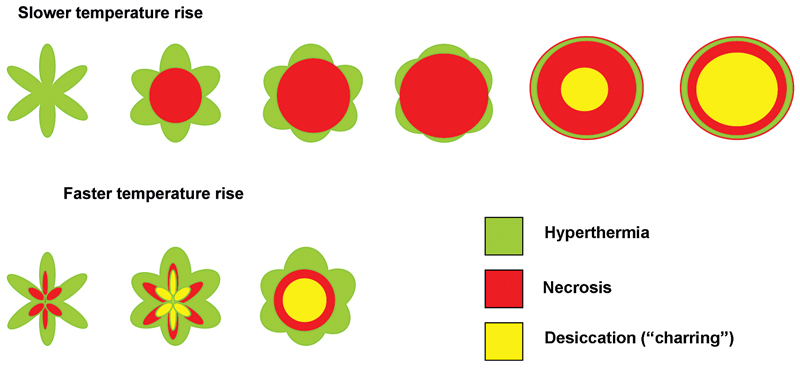
Fig. 1.4 A “thought” experiment using an umbrella-type radiofrequency probe seen in cross section. The top row shows an eventual larger zone of ablation compared with the bottom row. This is so because the faster increase in energy input (bottom row) results in a faster temperature rise in the tissue immediately around the probe. This tissue is charred before the maximum ablation zone is achieved. Once charring occurs, further energy deposition is impossible, as resistance is too high.
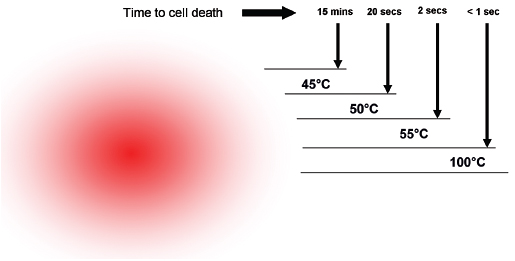
Fig. 1.5 The time needed for tissue death at various temperatures. Mammalian tissue is very sensitive to temperature changes. At 55°C, for example, tissue death results within 2 seconds. At 100°C, death is instantaneous as evaporation occurs. This is not desired in radiofrequency ablation, however, because of the insulating effect of charred tissue. Thus a slow, methodical energy deposition is more effective than a quick temperature rise.
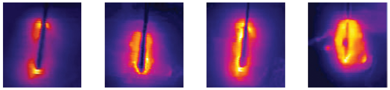
Fig. 1.6 Progression of a radiofrequency ablation by color representation of surrounding slow thermal changes without charring.
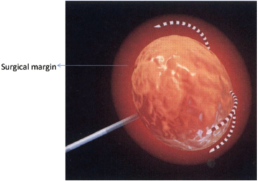
Fig. 1.7 A zone of 1-cm surgical margin beyond the visible tumor confines.
Data in RFA of liver primary tumors have demonstrated that 3 cm or less is the optimal size, and there is a persistent effort to improve and enlarge ablation size, through improved RFA techniques. Goldberg and Dupuy6 simplified an approach to the basis of RFA: Induced coagulation necrosis = (energy deposited × local tissue interactions) − heat loss. Investigators have suggested different approaches to solve these physical constraints by modulating tissue characteristics, increasing RF energy deposition, or modifying blood flow.
♦ Generators
Early RF generators for percutaneous application produced modest outputs of 50 W. Today, generators manufactured by the three major RFA companies in the United States are all capable of outputs of 150 to 200 W, delivering high-frequency (460–500 kHz) alternating current via RF electrodes (usually 14- to 17-gauge) of varying configurations. However, the three systems have distinctly different electrode designs and philosophies, varying energy deposition algorithms, and ablation end points. No definitive data have shown one system to be superior to another. Despite the company-suggested algorithms, there is great variability among users. Personal preference and familiarity still play distinct roles in the best and most consistent achievable patient outcomes.
♦ Electrode Modifications
Given the limited ablation zone with solitary electrodes such as the Bovie knife, a clear need was identified to increase the zone of necrosis by elongating the active areas in any given system. Modifications included developing expandable electrodes or using several straight electrodes in a cluster. These designs resulted in cylindrical ablation zones that did not uniformly conform to and cover the typical spherical nature of most small malignancies. As a further modification, the ability to place up to three single electrodes individually has been used as well to increase ablation size. With this technique, it is crucial to keep the active tips parallel and approximately 1 cm apart. With increasing inter-electrode distance, the area of coagulation can have a dog bone or dumbbell shape, with the potential for leaving remaining viable tumor between the electrodes. This illustration is particularly important when building compound ablation areas (overlapping ablations) for large tumors (>5 cm) (Fig. 1.9).
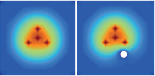
Fig. 1.8 The heat-sink effect is a phenomenon that limits the effectiveness of all thermal ablation methods. When the target lesion abuts a blood vessel that is 3 mm or larger, the flowing blood prevents large temperature variations in the part of the tumor near the lesion, thereby keeping the tissue “cooler.”
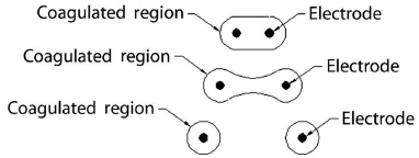
Fig. 1.9 If the electrodes are placed to far apart (>1 cm), the resulting overlapping area of affected tissue would change shape. As the distance between electrodes increases, the area of coagulation would have a “dog bone” or “dumbbell” shape. As the electrodes are placed further apart, this shape would evolve into distinct and separate areas immediately around each electrode, leaving viable tumor/tissue in between. This factor is particularly important when building compound ablation areas (overlapping ablations) for large tumors >5 cm.
Multitined Expandable Arrays
Improving on the original single monopolar needle, LeVeen described a novel approach of having multiple curved uninsulated prongs deployed from the needle tip central cannula, creating the shape of an umbrella. Each prong caused a separate area of coagulation necrosis that slowly increased in size by administering increasing amounts of RF energy in a stepwise fashion and eventually coalescing with the neighboring prong, creating a reproducible volume of necrosis (Fig. 1.10). Currently, this type of system is represented commercially by the LeVeen device (Boston Scientific, Natick, MA) (Fig. 1.11A). Other manufacturers pursued a stepwise deployment in a forward-orienting electrode, for example the Starburst XLi probe (AngioDynamics Inc., Queensbury, NY) (Fig. 1.11B).
Internally Cooled Electrodes
Goldberg described in 1996 an innovative approach whereby chilled saline is pumped through the chamber shaft of the needle, with the resultant reduction in charring and impedance, and increased tumor volume ablation.6 Cool-Tip electrode (Covidien, Boulder, CO) is the commercial prototype for this concept, which was then modified further by clustering three electrodes together (Fig. 1.12) for a synergistic coalescence of each thermal ablation.
Perfusion Electrodes
Perfusion electrodes were developed whereby saline or hypertonic saline is injected or infused into target ablation tissue, capitalizing on the concept that high local sodium chloride ion concentration can expand the volume of tumor ablation by altering tissue electrical conductivity. Commercial examples of perfusion electrodes are the XLi-Enhanced and Talon electrodes (AngioDynamics Inc., Queensbury, NY), which are multitined devices with saline pump perfusion enhancement, creating ablation diameter volumes of up to 7 cm.
Bipolar Radiofrequency Ablation Electrodes
A recent advance has been the development of bipolar systems, whereby two or more bipolar electrodes are placed into the tumor, and the applied RF current runs from one electrode to another without the need for grounding pads. This essentially ensures that all electrodes within the tumor are active, with minimal energy loss, allowing greater ablation volumes more efficiently and faster. Bipolar systems also do not require grounding pads and negate the risks of skin pad burns. The InCircle bipolar device (RFA Medical, Freemont, CA) is a U.S. Food and Drug Administration (FDA)-approved system that is compatible with most available generators from other manufacturers. The InCircle electrode is unusual in that two probes are placed on each side of the tumor without penetrating the integrity of the lesion, and the electrode surrounds the lesion (Fig. 1.13). This electrode may be helpful in circumstances where mobile or hard tumors may not have to be penetrated. This bipolar system attains large burns quickly in early reports, and may show promise for larger ablation volume compared with monopolar RFA. There are several other systems available in Europe and Asia.
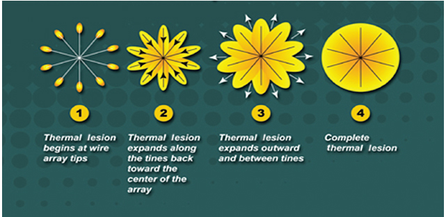
Fig. 1.10 Concept diagram of coalescing areas of coagulation necrosis from a multitined electrode.
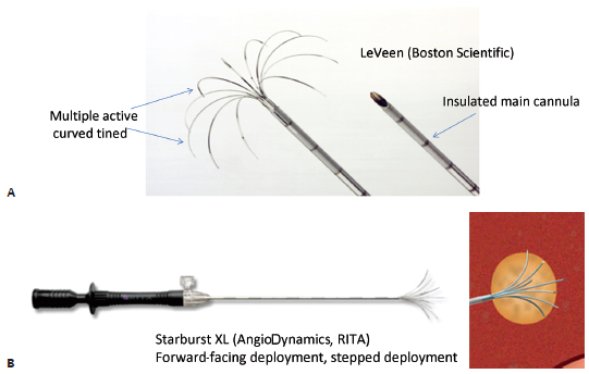
Fig. 1.11 (A,B) Multitined radiofrequency electrodes.
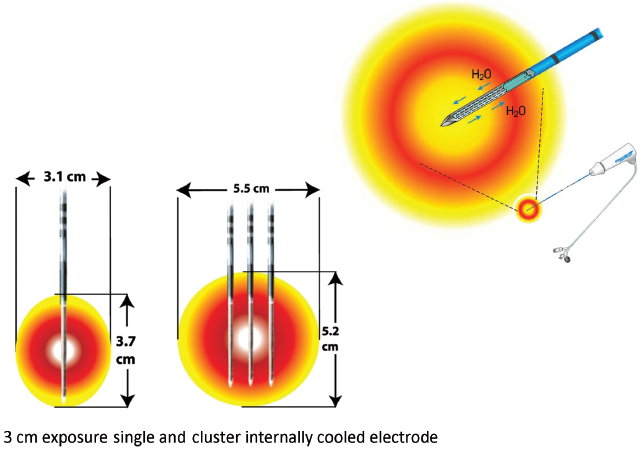
Fig. 1.12 Internally cooled electrodes. (Courtesy of Covidien.)
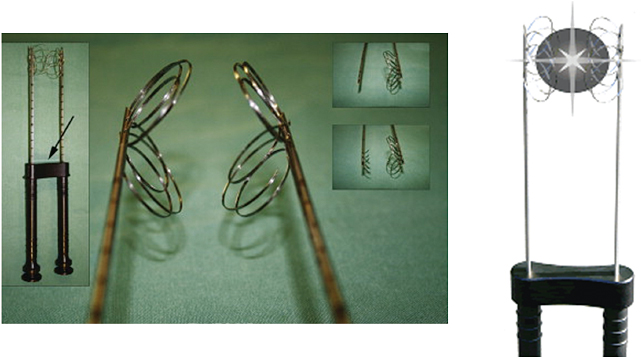
Fig. 1.13 Bipolar InCircle electrode. Two electrodes are placed parallel around the tumor, with each probe being an active energy pole. The arrow denotes a guiding spacer to optimize the distance between the poles of the circuit.
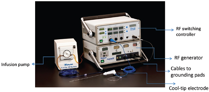
Fig. 1.14 Covidien Cool-Tip RFA system. (Courtesy of Covidien.)
♦ Commercially Available Radiofrequency Ablation Systems
For use in clinical practice, there are three major manufacturers of FDA-approved monopolar RFA devices on the market in the United States. All three systems reflect the key design modifications in the development of the RFA electrodes in their product line and intellectual property, and all were initially spurred by the desire to overcome the physical constraints of RF energy deposition in tumor tissue. They differ in the power of the generator, the technique used to maximize treatment volumes, the size of the needles, and the electrical parameters monitored to maximize energy deposition. Although temperature and impedance are measured in several of the systems, each system uses one parameter to maximize treatment diameter, and each system has a specific algorithm for treatment that requires varying degrees of operator input. Each system, with its generator and electrode range, has strengths and drawbacks, and ideally, operators should have access to more than one system. Familiarity with the system chosen by each operator is important when starting a new ablation practice, and all companies have robust sales and marketing divisions that can provide appropriate treatment algorithms and guidance.
Covidien (Formerly Tyco Healthcare Valleylab)
This system features monopolar single straight electrodes that internally circulate chilled water to cool adjacent tissue (Fig. 1.14). This decreases charring and vaporization, and thus increases ablation volume and shortens ablation time. The Valleylab RF Ablation Generator with Cool-Tip electrode technology features a feedback algorithm that continually monitors tissue impedance and adjusts it to achieve the appropriate energy output for each electrode, based on tissue impedance and tip exposure. The pulsed ablation system also allows tissue to rehydrate during the ablation cycle, minimizing rapid tissue impedance elevation that could limit RF output. The Valleylab RF Ablation System with Cool-Tip electrode technology has 510-k approval from the FDA for use in nonresectable liver tumors and osteoid osteomas.
Covidien also offers a cluster electrode composed of three electrodes contained within one handle (Fig. 1.15). The cluster electrode creates a 4-cm-diameter ablation zone. Covidien offers four electrode lengths and four tip exposures for customized ablation. Larger ablation zones can also be created with the Valleylab RF Ablation Switching Controller with Cool-Tip Technology, which allows the use of three electrodes simultaneously (Fig. 1.16). Also, the needle for the Valleylab RF ablation electrodes is 17-gauge, and the desired electrode tip is placed optimally to the end and slightly beyond the distal margin of the target lesion. Tract ablation is possible with the depression of the tract ablate button on the generator coupled with a slow withdrawal of the electrode.
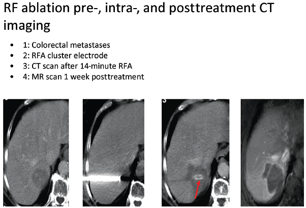
Fig. 1.15 Intraprocedural images from liver Cool-Tip ablation with cluster probe, for the treatment of colorectal metastasis.
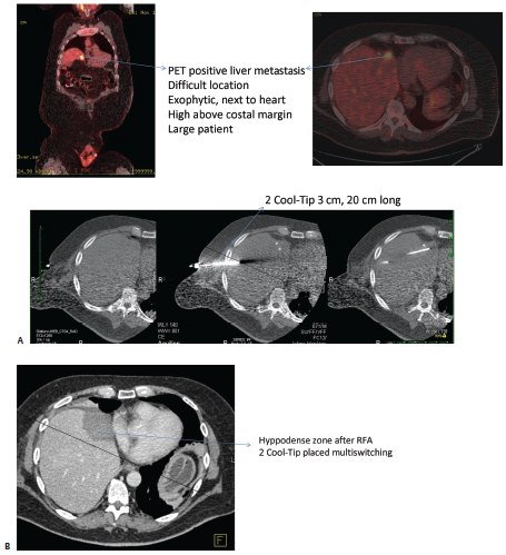
Fig. 1.16 (A) Intraprocedural images from liver Cool-Tip ablation with two single electrodes placed in parallel through a switching controller. (B) Eighteen-month follow-up computed tomographic liver scan after a liver radiofrequency ablation shows hyodense zone with no residual lesion. Positron emission tomography is negative; carcinoembryonic antigen is 0.6.
Valleylab Procedure (Table 1.1)
| Tumor Size (cm) | Number of Ablations | Needle Type |
|---|---|---|
| <1 | 1, 2, or 3 | Single |
| 1–1.5 | 1, 3 | Single |
| 1.6–2.5 | 1 | Triple cluster |
| 2.6–3.5 | 5–6 | Triple cluster |
| 3.6–5 | >6 | Triple cluster |
- Hook up all lines according to the manufacturer’s guidelines.
- Place the needle to the far end of the thermal lesion.
- Turn on the generator first, then the water pump, after verifying the temperature rise. Start with low current (100–800 mA) for a minute or two before ramping up to higher current. In pulsing mode, the current maximum will take care of itself, based on tissue impedance. Peak currents should be maintained for more than 10 seconds.
- Treat for 12 minutes. Turn off the generator and the pump simultaneously, and wait 30 seconds for maximum temperature. This is usually 60° to 90°C. If less than 70°, there is likely a vessel near the probe tip, and a repeat treatment in a slightly different area is required.
- When removing the electrode, push the “tract ablate” button while pulling the electrode out.
- Perform tract ablation on removal of the electrode, if desired.
- Perform post-RFA imaging to rule out complications.
- Treat for 12 minutes. Turn off the generator and the pump simultaneously, and wait 30 seconds for maximum temperature. This is usually 60° to 90°C. If less than 70°, there is likely a vessel near the probe tip, and a repeat treatment in a slightly different area is required.
Boston Scientific
Power is derived from a 480-kHz generator (RF 3000, Boston Scientific) capable of producing a maximum power of 200 W. The Boston Scientific system also features an impedance-based feedback algorithm that continually monitors tissue impedance and adjusts it to achieve the appropriate energy output for each electrode, based on tissue impedance and the type of electrode tip. The Boston Scientific RF procedures are performed with a monopolar array-type electrode with an umbrella-like deployment configuration (LeVeen; Boston Scientific) with diameters of 2 to 5 cm in increments of 0.5 cm and in various lengths (15-gauge), with 2-cm and 3-cm probes also available in a smaller gauge size (17-gauge), useful in high-risk access sites (Fig. 1.17). All electrode probe tips are active and give impedance feedback. The umbrella-shaped LeVeen electrode is expanded once the electrode is placed under guidance in the center of the target lesion, and the umbrella-like tines are deployed; the position of the tines is verified through imaging before commencing the ablation (Fig. 1.18). A single straight electrode is also available for small lesions (Soloist electrode), in 17-gauge size. Boston Scientific has an introducer coaxial system that allows computed tomography (CT) scanning with needles in place (without bulky hubs), and multiple needle placement for treatment planning and convenient pre-RFA biopsy without the need for reaccess.
Power from the RF generator (RF 3000, Boston Scientific) is delivered in a stepwise algorithm that provides starting powers of 20 to 80 W and increases 5 to 10 W/min to maximum values of 55 to 200 W. The end point of ablation with the Boston Scientific device is a dramatic increase in impedance (termed “roll-off” by the manufacturer). The standard algorithm suggests a second “burn” starting at 70% of maximum roll-off power (W). At the end of the procedure, tract ablation (to reduce needle tract seeding) is possible by retracting the prongs, and the probe is pulled back slowly by continuously applying 30 W if needed.
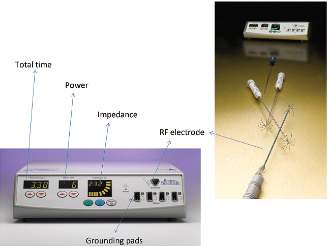
Fig. 1.17 Boston Scientific RFA system. (Courtesy of Boston Scientific.)
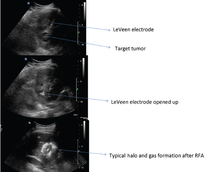
Fig. 1.18 Ultrasound-guided liver RFA with LeVeen Boston Scientific system for the treatment of hepatocellular carcinoma.
Boston Scientific Procedure
- Use image guidance (ultrasound, CT) to find the safest access site and to determine patient positioning.
- Place two ground pads on the patient’s thighs (two per leg), with both pairs equidistant from the ablation site. For extremity lesions, the pads may need to be placed on the lower trunk. If the patient is extremely hairy, consider shaving the ablation field first.
- Choose the appropriate LeVeen probe size (from 2 to 5 cm), generally using a size 0.5 to 1 cm larger than the target lesion.
- Deploy the probe tines fully once the probe has been placed into the center of the lesion. Verify the position of the tines and the probe on imaging.
- Push the start button on the generator; check the manufacturer-recommended starting power for the probe size, and generally increase the wattage by increments of 10 W/min (check the specific probe algorithm).
- When impedance “roll-off” is reached, the generator will stop. Wait 30 seconds, and restart the second burn at 70% of the last maximum power reached.
- In a large lesion, reposition the probe into a different site and restart the algorithm.
- At the end of the ablation, consider doing a tract ablation (reduce needle tract seeding) by retracting the tines to almost full retraction, select a generator power output of up to 30 W, and pull the probe back slowly while watching the impedance reading.
- Perform the end-of-procedure scan to check for complications.
RITA Medical Systems, AngioDynamics Inc.
RITA uses a temperature-controlled 460-kHz generator (model 1500X, RITA Medical Systems, Mountain View, CA) capable of producing a maximum output of 250 W. RITA has several electrode options, with the 15-gauge Starburst XL probe as the mainstay, capable of ablations from 3 to 5 cm; the probe contains nine deployable curved tines (Fig. 1.19). When fully extended, the maximum diameter is 5 cm; the probe has the configuration of a Christmas tree. The tips of the RITA hooks have thermocouples that report real-time temperature at the treatment volume margin as the tissue heats up, which automatically maximizes treatment volume. Real-time temperature readings are displayed on the generator console, measured at the five probe tips. RITA has a versatile range of flexible electrodes (Starburst Flex, Starburst SemiFlex) to mitigate CT gantry constraints, and has the only FDA-approved magnetic resonance imaging (MRI) device (Starburst MRI) and a smaller Starburst SDE for small ablations (2 cm). RITA has an additional saline-infusion system (Intelliflow Pump) that infuses saline into the ablation zone for the purpose of enhancing ablation by reducing charring (Starburst XLi-enhanced, for up to 7 cm). The Starburst Talon has side deployment tines for lesions that are difficult to access (Fig. 1.20). Coaxial access is possible with the soft and hard introducer. At the end of the procedure, tract ablation is possible with the RITA system by retracting the prongs and pulling back the probe slowly while maintaining the 70°C reading. Ideally, the probes should be placed at the proximal portion of the target lesion, allowing the tine tips to be deployed forward in a Christmas-tree shape (except for the Starburst Talon, which uses distal lesion placement and side deployment).
RITA Procedure
- Place the grounding pads on the patient’s thighs; the numbers differ for different RITA probes, so check the manufacturer’s guidelines.
- When using the Intelliflow Pump system in the Starburst XLi and Talon, with adjuvant saline perfusion, the peristaltic pump must be primed and tested prior to probe insertion; follow the manufacturer’s guidelines for setup.
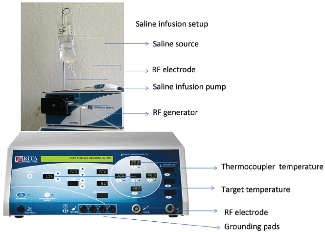
Fig. 1.19 AngioDynamics RITA RFA system. (Courtesy of AngioDynamics.)
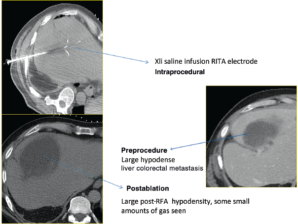
Fig. 1.20 AngioDynamics RITA XLi electrode, the largest ablation size diameter available commercially. It is used here for the treatment of a large, 5.2-cm, liver colorectal metastasis.
- The probe is placed into the lesion under image guidance. The optimal tip site is the proximal portion of the lesion to allow forward-facing tines to deploy outward into the lesion in a Christmas-tree configuration.
- Verify with imaging that full deployment has been safely achieved.
- Deploy the tines in stages to achieve incremental size and temperature targets: marks of 2 cm, 3 cm, 4 cm, 5 cm, …, with power set to 50 W, 70 W, 90 W, 110 W, …, and target temperature at 80°, 105°, 110°, …, and treat for specific time intervals or until the target temperature is reached. If the target temperature is not reached at any stage within 3 minutes, increase the power by 20 W. If the target temperature is still not reached, rotate the probe to move out of the vessel.
- Perform track ablation on removal of electrode by pushing the “tract ablate” button.
- Perform post-RFA imaging to rule out complications.
- Verify with imaging that full deployment has been safely achieved.
- RFA is the most frequently used ablative technique and has the longest track record. It should remain the primary ablation device, particularly for lesions <3 cm, and should be the cornerstone of any ablation practice.
- The RFA probe acts as the cathode of an electrical circuit that is closed by the application of dispersing grounding pads on the patient’s thighs. Any break of this circuit can cause electrical short and complications (burns).
- As one moves away from the source (electrode), energy deposition and temperature drop exponentially. The RF electrode itself is not the source of heat and is not hot to the touch.
- Proceed with RFA slowly and resist the temptation to increase power rapidly or bypass the generator algorithms, which will lead to tissue charring and incomplete ablation or residual viable tumor.
- Make sure to ablate a zone of healthy tissue (surgical margin) of 0.5 to 1 cm around the tumor; err on the side of caution if the tumor margins are not symmetrical. and choose an ablation size that is larger rather than smaller.
- Be aware of tissue heating loss, such as the heat sink from adjacent blood vessels. Consider adjuvant techniques (Pringle maneuver, angioplasty balloons to slow the flow).
- All RFA systems are effective and no one system has been shown to be superior. One must be familiar with the system chosen, and be comfortable in its operation. It is critical to combine technical knowledge with tumor geometric three-dimensional (3D) perspective when ablating. Leaving viable tumor behind is almost the same as not ablating at all.
- All systems are excellent at ablating small lesions <3–4 cm. For larger lesions, consider using adjuvant techniques to increase tumor kill (flow disturbance, intraarterial, combination therapy).


