The Physics and Dosimetry of High–Dose-Rate Brachytherapy
 NATURE OF HIGH–DOSE-RATE BRACHYTHERAPY
Conventional brachytherapy was developed very soon after the discovery of radium. The limited amount of radium that could be packed into the needles and tubes dictated the use of many sources to deliver a treatment dose through a target volume, and even with many sources, the delivery of the dose-required durations from 1 day to 1 week. For the most part, when new radionuclides became available, they matched the strength of the radium sources to facilitate application of the clinical experience gained through the decades of radium treatments. This conventional treatment format describes low–dose-rate (LDR) brachytherapy, as discussed in detail in Chapter 22.
Beginning around 1962, a new approach to brachytherapy developed. Using very intense, small sources (usually of 60Co in the early machines and often three in number) on the ends of cables, a treatment unit would move the source through the volume to be treated, delivering the radiation in a relatively short time (<1 hour). The rapid treatment delivery gave these treatments the name high–dose-rate (HDR) brachytherapy. The original units most often oscillated the source through a catheter’s treatment length, a method in common use until the modern generation of units developed in the early 1980s, described later. The treatments took so little time that the therapy proceeded on an outpatient basis. However, for reasons discussed later in this chapter, the treatment regimen usually entailed several fractions delivered over days or weeks.
The modern HDR units move a single source through the treatment volume in a stepwise fashion, moving at intervals, determined by the machine construction and the operator, to positions where the source pauses (dwell positions) for durations (dwell times) determined through optimization procedures.
Advantages and Disadvantages
Advantages of HDR brachytherapy over LDR include the following:
1. Optimization. The stepping-source design permits very fine control of the source position through the target volume. In most treatments, the determination of the dwell times comes from inverse planning, that is, specifying the doses desired at various locations and using some algorithm to calculate the dwell times that best fit the dose specifications. The map of how long the source dwells at each possible dwell position can be finely tailored to the geometry and needs of the particular patient because of the wide range of dwell times available. This process constitutes optimization. Although optimization is possible and frequently used with LDR applications, it forms a more natural part of the planning process with HDR brachytherapy.
2. Immobilization and stability. The relatively short duration of the HDR treatments allows better stability of many intracavitary treatment applicators during the treatment and, thus, higher precision in conforming the dose to the target. In addition to simply not giving much time for applicator motion, the applicator and the patient can both be immobilized with respect to the treatment table over the duration of the treatment. Such fixation is not possible with LDR brachytherapy because the patient would not tolerate the immobility for long periods. Interstitial cases may or may not exhibit better stability. The needles often tend to slide outward over the time that prostate implants remain in the patient, even with a template sutured to the patient that fixes the needles. In such a patient, the needles’ positions require adjustment before each fraction but move very little during the treatment delivery. Performing the same treatment using LDR brachytherapy would include needle movement during the long, slow delivery. On the other hand, head and neck implants with buttons anchoring the catheters at both ends may allow very little movement from the time of insertion through removal. Such cases would not find improvement in stability with HDR brachytherapy.
3. Dose reduction to normal tissue. Again, the short duration of HDR intracavitary treatments often allows displacement of normal tissue structure to a greater extent than with LDR treatments. This holds true for gynecologic and oral intracavitary cases but not for intraluminal applications, such as endoesophageal or endobronchial treatments. Most interstitial cases cannot make use of this feature since the needles or catheters fix all the tissues in place. Exceptions are mostly in the head, where the tongue sometimes can be moved away from the treatment site.
4. Outpatient treatment. Most HDR patients receive treatment as an outpatient. Exceptions include patients with indwelling needles such as prostate or gynecologic implants delivered in multiple fractions. Patients containing plastic catheters (i.e., not with sharp needle tips poking into flesh) almost always leave the hospital between fractions. All intracavitary treatments are on an outpatient basis. Outpatient treatments present many advantages over the inpatient treatments characteristic of LDR brachytherapy:
• Patient comfort. Patients confined to a room during LDR treatments often feel closed in. Compounding the claustrophobic effects, radiation safety considerations limit the time nursing staff can spend with the patient (sometime very severely), leading patients to feel like a pariah.
• Patient health. Many LDR brachytherapy applications require the patients to stay in bed, increasing the probability of thrombosis or bedsores. Although pneumatic socks greatly reduce the likelihood of thrombosis, aching muscles from immobility still create discomfort. In many cases, patients who could not tolerate protracted LDR treatments will be able to receive their treatments using HDR techniques.
• Economics. The cost of staying in the hospital greatly exceeds that of outpatient treatment. Counterbalancing the cost of hospitalization, the costs of the HDR remote afterloading equipment far exceed those for LDR applications. However, the HDR equipment costs quickly become amortized with a modest patient load, whereas the hospitalization costs remain constant for each LDR brachytherapy patient.
5. Less discomfort due to small size. Because the encapsulated HDR source is only 1 mm or less in diameter, the gynecologic intrauterine tandem need only be 3 mm in diameter, compared with 7 mm for the standard LDR tandem. Another way of looking at this comparison is to recognize that the diameter of the HDR tandem equals the smallest-size dilator used to stretch the cervical os to accept the LDR tandem. Much of the pain and discomfort from a cervical cancer treatment comes during the dilation. Eliminating that step eliminates much of that pain. Some facilities use only light sedation for the HDR tandem insertion rather than a general anesthetic, as is common with LDR procedures.
6. Elimination of delays. When applications fail to follow a plan or when plans have to change due to a finding in the operating room during the procedure, HDR treatments can still proceed following localization with little, if any, delay. LDR treatments likely would require ordering new sources to match the new situation and a delay in treatment to await delivery. The HDR model eliminates extra charges accruing from multiple-source orders.
7. Intraoperative procedures. HDR brachytherapy allows treatment intraoperatively, with suitable shielding in the operating room. With the short duration for dose delivery, a surgeon can add placement of the applicator and treatment of the patient to surgery with little additional time.
8. Radiation safety. HDR brachytherapy eliminates radiation exposure to personnel.
Unfortunately, HDR brachytherapy carries with it the following disadvantages:
1. Radiobiology. Compared with low–dose-rate brachytherapy, HDR treatments have worse therapeutic ratios, that is, the amount of damage to tumor cells compared with damage to normal tissue cells for the same dose. The damage to both types of cells per unit dose increases with dose rate, but the increase is greater for normal cells. Just as with external-beam radiotherapy, which also is high–dose-rate delivery, fractionating the treatment mitigates this effect. Although LDR therapy usually entails a single session or two, most curative HDR regimens use three or more fractions. The next section discusses the radiobiology in greater detail.
2. Error hazard. The increased complexity of the procedures and the compressed time frame of delivery increase the probability of errors in the treatment compared with LDR therapy.
3. Potential for very high radiation doses to patients and unit operators following failure of the source to retract. The HDR source can deliver 7.4 Gy/min at 1 cm in the patient. If the source stops moving or separates from the drive cable, serious injury occurs in a short time.
4. Resources. HDR treatments demand more resources than LDR treatments:
• Personnel. Because many HDR treatments proceed quickly from placement of the treatment appliance to delivery of the treatment, all of the persons involved with the treatment must be available at the same time or in relatively quick secession. That means that the facility must have sufficient staffing to release these persons on demand of the HDR brachytherapy cases.
• Economics. The HDR afterloading equipment comes with a large initial investment (at the time of writing approximately $500,000 to $1,000,000), not including the significant costs of shielding the treatment room and the increased cost for all the treatment applicators and supplies.
Radiobiologic Dosimetry
Because of the radiobiologic disadvantage of HDR treatments, considerable care must be taken in planning the time course of the therapy regimen. The following discussion is intended as a supplement to that in the first two chapters of this book. One of the important tools for such planning is the linear-quadratic model for biologic response.
The Linear-Quadratic Model
The basis for the model for biological response to radiation stems from an approximation to the cell survival curves as shown in Figure 24.1.
Several models have been used over the years to describe the shape of the curve, each giving different insights into the interaction of the radiation and the organism irradiated. One of the more useful when investigating radiotherapy regimen is the linear-quadratic (LQ) model.1–3
This model approximates the cell survival, S, a function of dose, D, as

Like any model, this equation fits the curves well over a particular range—in this case, the ranges of doses and dose rates used in radiotherapy—which makes it useful. It can also shed some light on biological underpinnings. However, the model should not be seen as a true and complete description and explanation of a complex biological phenomenon.
The curves shown apply to a single exposure of the cells over a short period of time at given dose rate. As can be seen, the effect of dose rate markedly changes the survival of the cells. This discussion need only consider the two components of the exponent in Equation 1. Conceptually, the first term, αD, corresponds to damage to the cells when a single charged-particle track breaks both sides of a DNA molecule rung (e.g., both a guanine and a cytosine), referred to as a double-strand break. This form of killing the cells requires a double-strand break. The surviving fraction depends only on the dose, and the effect does not depend on the dose rate. The second term, βD2, represents damage done when one charged-particle path breaks the bonds on one side of the DNA rung, say the guanine, and a different track breaks the other side (the cytosine). After the break on the first side, called a single-strand break, the DNA attempts repair. Because of the remaining cytosine on the opposite side, only a guanine will fit into the hole left on the damaged side. The nucleus contains many free guanine molecules, and one will be attracted to the opening and heal the wound. The repair takes place with a half-time of Tbio, which corresponds to a repair rate of
FIGURE 24.1. Typical cell survival curves with dose on the abscissa and surviving fraction on the ordinate, for three dose rates. The curves in the figure used α/β = 3 Gy for normal tissue, α/β = 10 Gy for the tumor, and α = 0.35 Gy−1 and μ = 1.5 h−1 for both types of tissue.
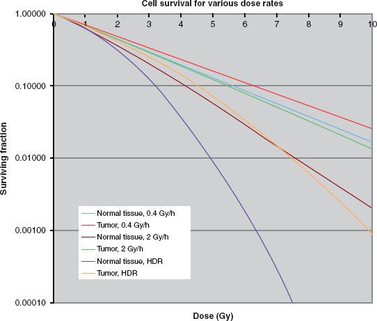

Because the repair takes some time, there is a window in which the second break must take place for the entire rung to be removed. If the second hit takes place after repair of the first, the damage still only forms a single-strand break, and the opposite side must be hit again to form a double-side break. Because forming a double-strand break in this way requires two independent hits, the probability follows D2. Because the second hit must occur before the repair of the first, the incidence of double-strand breaks depends on the dose rate. Frequently, calculations use a value for Tbio of 1.5 hours, although most normal tissues probably have a more complicated repair pattern, with a fast component of about 20 minutes and a longer one of about 2 hours.
The surviving fraction also depends on the values of α and β. These parameters are characteristic of the tissue being irradiated and the type of tissue injury being caused. The actual values are often not well known, and large variations in most tissues have been reported. However, in general, the values of α tend to be very similar for most tissues (within the uncertainties), with most of the variations being in the β term. Although the variations in the values determined for the two parameters tend to be large, smaller variation characterizes the ratio of α/β, the quantity most often given in the literature. For the most part, this ratio tends to be on the order of 2 to 3 for late effects in normal tissues and 5 to 20 for early effects. In general, tissues exhibiting less mitotic activity show lower values. Most tumors behave similarly to normal-tissue early effects but with a much wider range of values. Prostate cancer forms a notable exception, with an α/β between 1.5 and 2.
Figure 24.1 shows that as the dose rate increases, the fraction survival decreases for a given dose, and this effect is more marked for tissues with a low value for α/β. Thus, as stated earlier, compared with low–dose-rate brachytherapy, normal tissue has a comparative disadvantage for high–dose-rate brachytherapy. The usual approach to overcome the disadvantage fractionates the dose delivery. Figure 24.2 shows a survival curve with the dose delivered in several fractions. The pauses in the delivery allows repair of those single-strand breaks not converted into double-strand breaks by a second hit. Thus, at the beginning of each fraction the curve exhibits a new shoulder as the first single-strand breaks begin accumulating. The fractionation has no affect on the α term. Fractionation has a long history in external-beam radiotherapy, which, as noted, also is high–dose-rate delivery. Understanding the repair mechanism allows for a definition of what dose rates qualify as “high”: a delivery duration that remains much less than Tbio, or about 30 minutes.
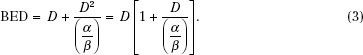
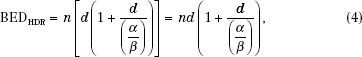
Surviving fraction does not depend directly on dose; instead, the whole exponent forms the independent variable. Because the α tends to be constant, it is often pulled out, leaving what is called the biologically effective dose (BED) or equivalently the effective radiation dose (ERD) as
For the fractionated, high–dose-rate irradiations, each new fraction starts the shape of the curve over but at the surviving fraction level where it left off at the end of the previous fraction (in the absence of proliferation), and the equation becomes
FIGURE 24.2. Survival curves illustrating the effects of fractionation. Again, the curves used α/β = 3 Gy for normal tissue, α/β = 10 Gy for the tumor, and α = 0.35 Gy−1 and μ = 1.5 h−1 for both types of tissue.
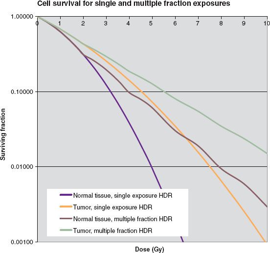
where n is the number of fractions and d is the dose per fraction.
The LDR situation becomes more complicated because repair takes place during the irradiation, reducing the effectiveness. In this case, BED becomes
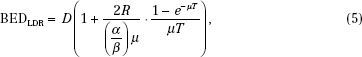
where T is the duration of the treatment and R is the dose rate. Because the BED depends on the α/β used, the convention when giving a value for BED requires that the units of gray carry a subscript specifying the α/β. For example, the BED of 10 Gy for late-responding tissue with an α/β of 3 might be stated as BED = 10 Gy3.
In fact, the equations for both modalities also contain a term, not shown in the equations,

to account for cell repopulation over the total treatment duration. Tpot represents the potential cell doubling time. Most applications ignore this term because of the large uncertainties in the values for α and Tpot. In situations comparing the BED of low– and high–dose-rate application where the total duration of the therapy would be approximately the same, this omission probably causes no significant loss of information.
Conversion from Low– to High–Dose-Rate Brachytherapy
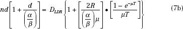
Often, when beginning an HDR brachytherapy program, the biggest questions relating to treatments become how many fractions to use and what dose per fraction. The larger the number of fractions, the better is the therapeutic effect, measured as the ratio of the damage to tumor cells to the damage to normal tissue cells. This ratio improves with each additional fraction, but the amount by which the ratio increases decreases with each added fraction. For example, going from four to five fractions improves the therapeutic ratio by 4%. Adding a sixth fraction improves the therapeutic ratio but only by another 3.5%. Each additional fraction carries with it costs in departmental resources (particularly the time of those persons involved) and inconvenience (and possibly discomfort) to the patient. Thus, selecting the number of fractions becomes a compromise. Most curative regimens use 5 or 6 fractions if applicator insertion procedures are involved and 8 to 12 fractions if the applicator can be left in place and the patient simply treated. Small-volume applications, such as vaginal cuff or most endobronchial treatments, may require only 3 or 4 fractions. After establishing the number of fractions, determining the dose per fraction comes next. One method that uses the LDR experience sets the BED equal for the two modalities and then solves for the dose per fraction:

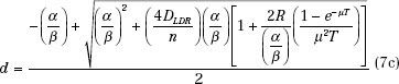
The absolute value for the dose per fraction depends on the ratio α/β, thus requiring another decision. Projecting d from the LDR experience, the normal-tissue toxicities could be held constant and an α/β of 3 used, or tumor cure could be the endpoint, suggesting an α/β of 10 (or a value of the particular type of tumor under treatment). Holding the late complications constant will lead to a BED for the tumor considerably less than was used with the LDR treatments, whereas attempting to achieve the same tumor control produces normal-tissue BED values much higher than those for the LDR regimen. For intracavitary treatments, the normal tissues sometimes can be held away from the applicator during the treatment delivery, for example, by keeping the rectal retractor in the vagina during a tandem and ovoid treatment. This would allow a dose based on equivalent tumor control. In interstitial applications, distance to the normal tissue in the implanted volume cannot be increased, but often with the improved optimization available with the HDR approach, high doses in the implant can be significantly reduced compared to conventional LDR implants, again allowing the dose based on tumor control. Seldom have HDR treatments produced more severe normal-tissue toxicities than those delivered at LDR. In general, the maximum significant dose, that is, the highest value of isodose surface that encompasses more than one catheter or needle track, should be kept to <150% of the prescription dose.
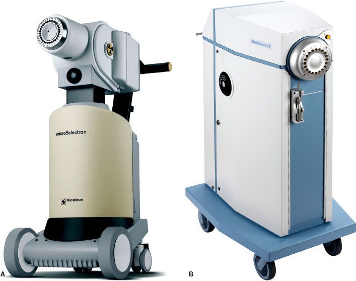
FIGURE 24.3. A: The Nucletron MicroSelectron. B: The Varian VariSource. (A, courtesy of Nucletron, an Elekta Company; B, courtesy of Varian Medical Systems.)
High–Dose-Rate Devices
Remote Afterloaders
A remote afterloader (RAL) is a computer-driven system that transports the radioactive source from a shielded safe into the applicator placed in the patient. On termination or interruption of the treatment, the source is driven back to its safe. The device may move the source by one of several methods, most commonly pneumatic or cable drives. A stepping-source RAL is a particular design of the treatment unit that consists of a single source at the end of a cable that moves the source through applicators placed in the treated volume. The treatment unit can treat implants consisting of many needles or catheters in the patient. Multiple catheters are often required to cover the target with uniform radiation doses. Each catheter or part of an applicator is connected to the RAL through a channel. The computer drives the cable so that the source moves from the safe through a given channel to the programmed dwell position for a specific dwell time. In any applicator, there may be many dwell positions. After treating all the positions in a given catheter (channel) the source is retracted to its safe and then driven to the next channel. There can be several dwell positions per centimeter in each channel, and the dwell time can vary from 0 to almost 1000 seconds in 0.1-second increments, thereby giving a high level of flexibility of dose delivery. All currently available HDR RALs use the stepping-source design. Four models of HDR RALs are available in the market, three in the United States: MicroSelectron (Nucletron, and Elekta Company, Veenendaal, Netherlands) and Gamma-Med and VariSource (both from Varian Medical Systems, Palo Alto, CA). In Europe, the Bebig MultiSource (Eckert & Ziegler BEBIG, Seneffe, Belgium) is also available. Figure 24.3 shows two of the units. Even though they may vary in details, all available HDR RALs consist of the same general components (Fig. 24.4): (a) shielded safe, (b) radioactive source, (c) source drive mechanism, (d) indexer, (e) transfer tube, (f) treatment control station, and (g) treatment control panel.
FIGURE 24.4. Components of a high–dose-rate brachytherapy remote afterloader. (Figure by Adam Uselmann after a draft by Liyong Lin.)
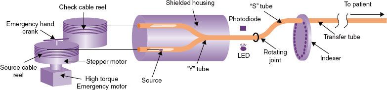
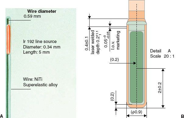
FIGURE 24.5. Diagrams of two HDR brachytherapy sources: for the VariSource (A) and for the MicroSelectron (B). (A, courtesy of Varian Medical Systems, Palo Alto, CA; all rights reserved; B, courtesy of Nucletron, and Elekta Company, Veenendaal, Netherlands.)
Sources
Whereas delivering the HDR brachytherapy requires an intense source, passing the source through needles placed through a tumor requires one of a small size. The radioactive source in an HDR RAL is usually 3 to 10 mm in length and <1 mm in diameter, fixed at the end of a steel cable. The Nucletron source is placed in a stainless steel capsule and welded to the cable, whereas the Varian source is placed in a hole drilled into the cable and closed by welding. Figure 24.5 shows diagrams of the sources. 192Ir is now used for almost all HDR RALs; the Bebig unit offer the choice of 192Ir or 60Co. 192Ir emits many photon energies, mostly between 110 and 704 keV, with an effective energy around 380 keV. A new source has an activity near 0.37 TBq (10 Ci, approximately 44 mGy m2 h−1). Because 192Ir has a half-life of 74 days, the source should be replaced every 3 months to keep the treatment in the HDR radiobiologic regime (see later discussion). The potential advantage of using 60Co is the 5.3-year half-life, extending the time between source changes to approximately 5 years. A trained medical physicist calibrates the source after each installation using a re-entrant, well-type ionization chamber, as discussed later. The resulting source calibration is verified against the manufacturer’s source calibration.
Recently, an afterloader came to market using a 169Yb source. The advantage of this source comes from the lower energy of its emissions, dominated by 63 keV (44% of the time) and 198 keV (36% of the time). The lower energy implies that shielding in any applicator reduces the intensity of the radiation to a greater extent than for 192Ir and also opens the possibility of including shielding in smaller structures, such as an intrauterine tandem.
Applicators
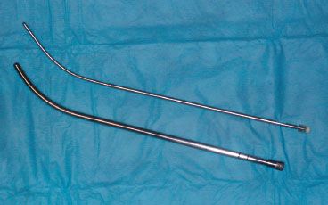
An array of applicators for different treatment sites is marketed by each vendor. Each vendor designs its own applicators that can only be used with its transfer tubes and HDR RALs. Before an applicator is used clinically, tests should be performed to verify the functionality of the applicator. It should also be radiographed with dummy sources (ribbons) to verify agreement with the vendor’s specifications. The length of each applicator, location of the dwell positions with respect to the applicator, and integrity of the applicators should be a part of the routine quality assurance (QA) program to ensure safe and precise delivery of the radiation treatment plan. Figure 24.6 shows a comparison between an HDR and a LDR intrauterine cervical tandem. The smaller diameter of the HDR applicator leads to greater patient comfort during the procedure. Because the high–dose-rate iridium source is much smaller than the low–dose-rate cesium tubes, high–dose-rate applicators have a smaller radius.
Pulsed Brachytherapy
Pulsed brachytherapy (also known as pulsed high–dose-rate brachytherapy or, not quite correctly but most commonly, pulsed dose-rate [PDR] brachytherapy), attempts to eliminate the unfavorable radiobiology of HDR brachytherapy while maintaining the ability to optimize finely the dose distributions and eliminate the personnel exposure to radiation. The pulsed brachytherapy unit is the same as an HDR unit except the source is shorter and only about 1/10 as active. The treatment also follows the same pattern as an HDR treatment, except that the patient remains in the hospital, and instead of 10 fractions, the source runs through the treatment once each hour. These hourly treatment pulses last only a few minutes, but the overall duration usually covers 1 or 2 days. Thus, biologically, because each fraction comes before complete repair of sublethal cellular damage, the tissues experience the radiation as almost continuous, mimicking LDR brachytherapy.
Although this approach incorporates the biologic advantages of LDR treatments and the optimization advantage of HDR brachytherapy, it also has many of the disadvantages of both modalities, including (a) inpatient treatments, (b) lack of applicator stabilization, and (c) possibility of mechanical failures. Because the source treats the patient 24 times per day, and each treatment includes three or more catheters, the number of source transits becomes quite large and many times more than for a normal HDR regimen. Such frequent source use increases the likelihood of source failure during a treatment. Should a source become caught during transit, the dose to the patient could become quite large. Unlike HDR procedures, the operator does not sit at the control panel always ready to retrieve a stuck source. Limiting the activity of the source to 1/10 of the normal HDR source allows 10 times the response time for a stuck source before significant injury to the patient. The other reason for the low activity is that, with the treatment divided into so many small fractions, the dwell times become too short for the treatment unit to control with a very active source. In summary, pulsed brachytherapy presents opportunities to potentially improve brachytherapy, but it also comes with detriments. PDR brachytherapy is discussed in more detail in Chapter 23.
FIGURE 24.6. HDR (top) and LDR (bottom) intrauterine tandems.
 OPERATION
Personnel Roles
The report of Task Group 59 (TG-59) of the American Association of Physicists in Medicine discusses the roles of the members of the treatment team for high–dose-rate brachytherapy.4 For the most part, the roles follow standard procedures for any brachytherapy, with the physician inserting the treatment appliance and prescribing the treatment; the nurse monitoring the patient’s condition and welfare; therapists or radiographers performing the imaging for localization; and the physicist assuring the correct calibration of the source. Who performs some of the functional roles discussed in what follows varies by institution but needs clarification so all persons involved understand the distribution of responsibilities.
Daily Quality Assurance
The tests of the treatment unit at the beginning of the treatment day often fall to the medical physicist. However, in some facilities, a therapist or dosimetrist performs the actual tests, and the medical physicist reviews the results of the tests before the first treatment.
Treatment Planning Calculation
The report of TG-59 discusses options for entering the patient data into the dose-calculation computer and generating the treatment parameters (dwell positions and dwell times).4 One model presented in that report had a dosimetrist running the program and a physicist monitoring the input to correct errors as they occur. Studies have shown that such supervision provides little protection against errors.5 Either a physicist or a dosimetrist may perform the treatment plan generation.
Quality Assurance on the Treatment Plan
Regardless of who generates the treatment plan, a medical physicist should review the plan for appropriateness and correctness. The reviewing medical physicist should not be the same person who generated the plan, so in facilities with only one medical physicist, a dosimetrist should perform the planning.
Delivery of the Treatment
Several factors enter into considerations of who should staff the control panel during the treatment. In some states, regulations dictate that only therapists may deliver treatments and control treatment units. The regulations in most states and from the U.S. Nuclear Regulatory Commission are silent on the issue. At the time of writing, regulations almost uniformly require the attendance of a medical physicist at the treatment (or within unamplified voice communication of the unit operator). As a result, many facilities have the medical physicist operate in the unit during treatments. One important consideration is that at least one person in the control area during treatments must be ready and willing to enter the room and take appropriate actions in case the source becomes stuck in the patient.
Normal Procedures
When the afterloader receives a command from the treatment control panel to initiate a treatment, the source cable advances from the shielded safe through the Y tube and then the S tube to the first channel in the indexer and then along a path constrained by transfer tubes to the first treated dwell position in the applicator (see Fig. 24.4). The source dwells at that position for a predetermined duration. After completing that dwell it goes on to the subsequent dwell positions. Some units step as the source drives out (MicroSelectron and Gamma-Med), stopping first at the dwell position most proximal to the afterloader, whereas in the other (VariSource) the source travels first to the most distal dwell (toward the tip of the applicator) and a bit farther and then steps as the source returns toward the safe. Stepping on the outward drive obviates any concern about the effect of slack in the drive mechanism affecting the accuracy of the source position. The unit that steps on the way back into the unit includes correction for slack in the calibration of the source location. On completion of the treatment for the first channel, the source is retracted into the safe and redirected to travel to the second channel. The process is repeated for all the subsequent treatment channels. The programmed movement of the source is verified by means of an optical encoder or other device that compares the angular rotation of a stepper motor or cable length ejected or retracted with the number of pulses sent to the drive motor. This system is capable of detecting catheter obstruction or constriction as increased friction in the cable movement. Under certain fault conditions, such as if the stepper motor fails to retract the source, a high-torque direct current emergency motor will retract the source.
The confirmation of the source exit from and return to the safe is carried out by an opto-pair, consisting of a light-sensitive detector and an infrared light source, which detects the cable when its tip obstructs the light path. All the currently marketed afterloaders are also equipped with check cables, or “dummy sources.” The check cable is an exact duplicate of the radioactive source along with its cable, except that it is not radioactive. Before the ejection of the radioactive source, the check cable is first ejected to check the integrity of the catheter system. After a noneventful check by this dry run with the dummy source, the radioactive source is then sent for treatment.
Emergency Procedures
Because HDR RALs are complicated devices containing very-high-activity radioactive sources, serious accidents can happen very quickly, thereby demanding many safety features and operational interlocks to prevent erroneous source movement or facilitate rapid operator response in the event of a system failure.
Door Interlock
Interlock switches prevent initiation of a treatment with the door open. Opening the door interrupts the treatment’s progress. This safety feature protects the medical personnel from radiation exposure in the event someone enters the treatment room without the knowledge of the operator. If a door is opened inadvertently during the treatment, the treatment is interrupted and the source returns to the safe. The treatment can be resumed at the same point where it was interrupted by closing the door and pressing the start or the resume button at the control panel.
Emergency Switches
Numerous emergency off switches are located at convenient places and are easily accessible in case a situation arises. One is located on the control panel for the HDR operator. Another is located on the top of the remote afterloader treatment head. Vendors also install two or more switches in the walls of the treatment room. In the event a treatment is initiated with someone other than the patient in the treatment room, that person can stop the treatment and retract the source by pressing the emergency off button.
Emergency Crank
In the event of the failure of a source to retract normally, as well as the failure of the emergency motor, all HDR RALs have emergency cranks to retract the source cable. Using the crank requires the operator to enter the room with the source unshielded.
Emergency Service Instruments
If the radioactive source fails to retract after termination or interruption, pushing the emergency switch, or cranking the stepper motor manually, the immediate priority is to remove the source from the patient. Because the source is in contact with the patient, it can cause severe injury in a very short time. However, working at a greater distance, it is unlikely that the operator will receive a dose exceeding regulatory limits for 1 year, let alone one that would cause health problems. Once the source is removed from the patient and moved to the distance of even 1 m, the exposure rate drops drastically, and actions can then be taken to remove the patient from the room safely.
The safest approach to a source that will not retract by any of the methods is to remove the applicator from the patient as quickly as possible and place the applicator containing the source in a shielded container. If it is clear that the cable is caught in the transfer tube and not in the applicator per se, the applicator may be disconnected from the transfer tube and the patient removed from the treatment room. In some cases, this will be faster than removing the applicator. The reason to avoid disconnecting the applicator from the transfer tube is that a source may stay in the applicator if the source capsule shatters or come free from the cable. In that case, removing the applicator attached to the transfer tube keeps the system closed, whereas disconnecting the two opens a path for parts of a broken source to fall from the applicator into body cavities or crevices or roll onto the floor.
A situation might arise when the source needs to be detached manually from the treatment unit. Such a rare situation might occur if the unit with an unretractable source fell on a person and could not be moved by hand (perhaps by something else falling on the unit). The source could be close to the person but not inside. In this situation, the source cable should be cut from the unit and the source placed in the shielded container always present in the room. In cutting the source cable, it must be clear that the cut is not through the source capsule. For units with the capsule welded on the cable, the cut must be through the braided cable as opposed to the smooth steel capsule. For sources imbedded in the cable, a sufficient length of the cable must be seen to ensure that the cut occurs behind the source. Thus, emergency tools that must be present in the treatment room and always readily accessible include a wire cutter, a pair of forceps, and a shielded service container. The source should never be cut from the cable while the source is still in an applicator in the patient!
 FACILITY DESIGN
The radioactive source in the high–dose-rate machine starts about at 10 Ci with an in-air equivalent dose rate at a distance of 1 m from the source of about 44 mSv/h. According to the rules and regulations of the Nuclear Regulatory Commission (NRC), the annual limit for radiation exposure to the public is 1 mSv and the annual occupational limit is 5 mSv. (The actual limit for occupational exposure is 50 mSv/y, but following the principle of maintaining exposures as low as is reasonable achievable, the NRC usually holds licensees to exposure 1/10 of the actual limit.) In addition to the annual limit, NRC requires that in an unrestricted area the dose equivalent rate should not be more than 0.02 mSv in any hour. Thus, the high–dose-rate machine needs to be housed in an adequately shielded room. To meet these requirements in an HDR suite, where the walls and the ceiling are at least 5 feet from the machine head, concrete walls of about 43 to 50 cm (or 4 to 5 cm of lead) are needed. For larger rooms the concrete wall thickness will be lower because the exposure rate is inversely proportional to the square of the distance from the radioactive source. The tenth-value layer thicknesses for 192Ir are 1.6 cm and 15 cm of lead and concrete, respectively. For details on the procedures for calculating the thickness of barriers for a particular facility, see a health physics text such as that by Cember and Johnson,6 McGinley,7 or the report from the Nation Council on Radiation Units and Measurement.8
Imaging plays an important part in most brachytherapy, so consideration of required imaging modalities should enter into the room design. If the facility will perform a significant amount of gynecologic intracavitary insertions, fluoroscopic and radiographic equipment in the room saves a considerable amount of time and eliminates the motion inherent in moving the patient between rooms for imaging and treatment. Also for gynecological cases, ready access to magnetic resonance imaging should be considered. Having space and access for anesthesia in the room facilitates HDR brachytherapy for prostate cases.
All HDR brachytherapy rooms must have video and audio communication for monitoring the patient. Radiation detectors for monitoring the radiation levels in the room and indicating when the source is out of its shielding also are required.
 QUALITY CONTROL OF THE REMOTE AFTERLOADING DEVICE
Several of the disadvantages of HDR brachytherapy concerned the probability of failure, either human or mechanical. Both aspects of the treatments require effective quality management. This section deals with quality assurance for the treatment unit. One report from the American Association of Physicists in medicine discusses this topic,4 as do fundamental publications by Ezzell,9,10 Chenery et al.,11 Flynn,12 Grigsby,13 Jones,14 and Meigooni et al.15 Williamson et al.16 assembled much of the important material into a chapter. For a fairly comprehensive discussion, the reader is directed to Thomadsen.17
As for any piece of radiotherapy equipment, the QA begins with acceptance testing and commissioning. Periodic QA includes tests performed with each new source (approximately quarterly for most units) and those at the beginning of each treatment day. Of all of these, the daily morning checks form the basic set of essential tests.
Morning Checks
Although the list of safety checks seems long, the evaluation need not consume a great deal of time. At our facility, the entire morning routine takes about 10 to 15 minutes. Most of the items could be tested in numerous manners, but only one set of techniques will be discussed here. Individual units may differ in the exact methods. The procedure in the list often assumes the successful completion of all of the items going before. Failure of any item requires evaluation by the physicist of the appropriateness of continuing with patient treatments in light of the particular failure. The morning checks focus on ensuring that the unit is operating safely and correctly.
Safety Checks
The following items should be considered in a safety check:
Communication equipment. See that the television and intercom systems function.
Catheter-attachment lock. Attach a transfer tube to one of the channels of the unit, but do not lock the transfer tube in place (often accomplished by the locking ring). Program the unit to send the source to a dwell position that would be in an applicator were one attached, and initiate a source run. A program time for a single dwell of about 20 seconds would allow execution of the tests to follow. The unit should detect that the transfer tube has not been locked in place and prevent the source run. Were a treatment to take place in this condition, the source cable could push the transfer tube out of the unit and never enter the applicator.
Applicator attachment. Keeping the same program, lock the transfer tube in place but still do not attach an applicator to the transfer tube. Again attempt to initiate a source run. The check cable run should detect the absence of an applicator and prevent sending out the source. Failure of the unit to detect this situation could lead to the source indicating that it treated a catheter when in reality the catheter was never attached. This test also checks that the unit will not send out a source if the pathway is blocked, because for most transfer tubes, the applicators push aside a blockage of the tube when they lock in place.
Door interlock. Lock an applicator into the transfer tube. For future tests it is convenient to use a needle in a well-type ionization chamber. Keeping the same program as in the previous tests and with the door to the room open, try to initiate a run. The unit should refuse to initiate the treatment and indicate that the door is open.
Source-out indicators. Close the door, and initiate the source run. Observe that the indication lamps operate. Most rooms have three beam-on indicator lamps: one connected to a treatment-unit microswitch that triggers when the source leaves its shielded housing, one that lights when the signal on the radiation detector in the room exceeds its trip level, and one from the on-board Geiger counter. Let the exposure continue for the next test.
Room monitor audio operation. Listen through the intercom for the sound of the room radiation monitor. It should make a mild but clearly audible sound. It should not be too loud, for that would disturb the patient. There is no regulation in most states or with the NRC that the in-room monitor provides any audible signal. The presence of such a signal would alert anyone who is in the room unintentionally when the source is out. Some practitioners feel that any such signal causes concern on the part of the patient. We have tried both situations and have found that patients do not mind the signal if they have been informed that it would occur. Continue the exposure.
Room monitor visual operation. Open the door to the room and observe the visual indicators on the room monitor. The room design should provide protection to a person in the doorway until the source retracts. At the same time as this test is performed, so is the next.
Hand-held monitor operation. Immediately on opening the door during the previous test, hold the hand-held monitor in the doorway and see whether it indicates the presence of radiation. The hand-held detector is to be carried upon entry to the treatment room any time after a source run. Alternatively, the detector could be tested with a dedicated check source at the beginning of each day. Performing the test along with the room monitor makes the treatment unit the dedicated check source.
Door interrupt. During the previous two tests, the unit should have been retracting the source, beginning from the opening of the door. The retraction should take no longer than 4 to 6 seconds to return the source to its shielded location.
Emergency stop. Close the door and reinitiate the exposure. Once the source reaches the dwell position, press the emergency off button. The unit must immediately retract the source and likely require a reset.
Treatment interrupt. Reinitiate the exposure and once the source again reaches the dwell position, press the treatment interrupt button. Again, the unit must immediately retract the source.
Timer termination. Reinitiate the exposure and let it continue until the elapsed duration equals the time set on the timer. At that time, the unit stops the exposure and retracts the source.
Dosimetry Checks
The thrust of the dosimetry checks focuses on the delivery of the correct dose to the proper location.
Source Positioning Accuracy
Proper treatment requires that the source occupy the position along the catheter corresponding to that used in the treatment plan. The uncertainty of the determination of the dwell positions on the treatment plan is discussed elsewhere in this chapter. Here, the issue becomes duplicating the dwell locations on the treatment plan during execution. A usual criterion for coincidence with the planned treatment dwells is 2 mm, although the HDR units are able to place the source in a given location within 1 mm. Precision <0.5 mm begins to be less reproducible. To direct the source to correct locations corresponding to each dwell position, the source controller requires the distance along the catheter corresponding to the first dwell position. The distance may refer to the length from some part of the unit (such as the front face, the point of catheter insertion, or a microswitch that tells the unit when the source enters the catheter), or it may be from some fictitious point (similar in concept to the effective source for electron beams). Verifying that the unit can place the center of the source at a specified distance becomes an important part of the morning QA.
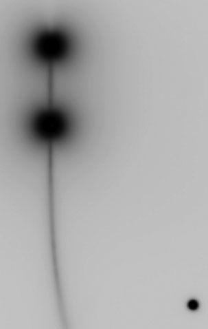
Three methods for verifying the source placement accuracy will be discussed here, although many others exist. The first method makes an autoradiograph of the source. After taping a clear catheter to a piece of paper-jacketed film (e.g., XV-2 “ready pac”; Carestream, Woodbrige CT) and inserting the x-ray marker wire, mark the position of the first dwell marker on the film. (This method assumes the x-ray marker to be correct. Verification of that is discussed with tests following a source replacement.) This can be done by using pinpricks or pressing hard with a ballpoint pen. If one is using a pinprick, the lights in the room should be dimmed and the film processed immediately after exposure. A pinprick at a far distance from the source track gives an indication of the amount of signal due to light exposures. If one is using a pen, lines about 1 cm long with an end at the center of the marker help to see the actual position. Pen marks must be strong enough to etch the film through the jacket but not so strong as to tear the jacket. With either technique, marking both sides of the catheter makes determining the center of the marker on the film easier. It is a good idea to establish that the unit not only places the source at the correct location for the first dwell position but also keeps track of relative positions. To do this, also mark some additional dwell positions, such as dwell positions 5 and 10 cm from the first. Program the source to stop at the marked positions for about 2 seconds each for a source with a strength of 0.04 Gy m2 h−1. The times for other source strengths vary in inverse proportion. Deliver the exposure and process the film. The resultant image looks like a dark blot, where the centroid indicates the effective center of the source. This centroid should fall between the marks, plus or minus the allowed tolerance. The distance to the centroid of other marked dwell positions should be much better than the absolute tolerance for hitting the first dwell position. Many factors influence the results of this method and interpretation of the results. One is the effect of light exposing the film when using pinpricks. To assess the size of the exposure due to light, poke a hole in the film well away from the catheter path. After processing, the dark blot by this hole should remain less than half the diameter of the holes marking dwell positions. If the light-leak hole shows a blot about the same size as the actual test holes, then the test holes mostly just indicate room light and provide no information about source positioning. Figure 24.7 shows a typical test film.
FIGURE 24.7. A typical image made to test the accuracy of the high–dose-rate unit source positioning.