Radiologic Evaluation of Allergic and Related Diseases of the Upper Airway
Achilles Karagianis
Michelle Naidich
Eric J. Russell
Anatomy
The complex anatomy, and the terminology used to describe the anatomy of the paranasal sinuses and nasal cavity, is best approached by first reviewing the normal drainage pattern of sinonasal secretions. Functional anatomy is intimately related to the pathophysiology of sinus inflammatory disease, and understanding it is critical to plan for functional endoscopic sinus surgery (FESS).
The anatomy of the sinuses can be viewed in two separate but interrelated groups: the sinuses themselves and their associated outflow tracts. There are paired frontal and maxillary sinuses, paired anterior and posterior ethmoid air cells, and a paired sphenoid sinus. Some radiologists consider the sphenoid sinus to be a single sinus subdivided by a sphenoid septum. There are three main outflow tracts for the paranasal sinuses: the ostiomeatal complex, the sphenoethmoidal recess, and the frontoethmoidal (frontal) recess (Fig. 10.1). The sinuses all eventually drain into the nasal cavity.
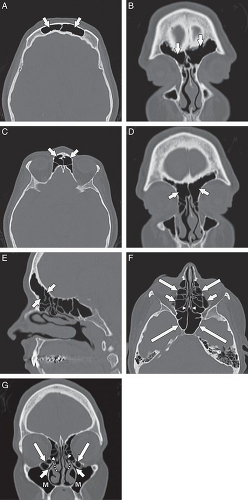 Figure 10.1 Normal sinus anatomy. All of the following are CT images utilizing a bone algorithm in either an axial or coronal plane. Axial (A) and coronal (B) images demonstrate the frontal sinuses (arrows). An axial image (C) slightly more caudal from image A demonstrates the frontoethmoidal recesses (arrows). Coronal (D) and sagittal (E) reformatted images also demonstrate the frontoethmoidal recesses (arrows). Axial (F) image demonstrates the anterior ethmoid air cells (large arrows) and posterior ethmoid air cells (medium arrows), the sphenoethmoidal recesses (arrowheads), and the sphenoid sinuses (large arrows). A coronal image (G) best demonstrates the osteomeatal complex including the infundibulum (arrows), uncinate process (U), hiatus semilunaris (arrowheads), and the middle meatus (dots). Haller cells are present bilaterally (medium arrows). The maxillary sinuses (M) drain into the osteomeatal complexes. |
The nasal cavity is divided vertically by the nasal septum. The anterior portion of the septum is cartilaginous (quadrangular cartilage) and the osseous posterior portion is comprised of the vomer inferiorly and the perpendicular plate of the ethmoid bone superiorly. The nasal vestibule is a paired air passage at the level of the nasal ala. The pyriform aperture is the osseous opening to the nasal cavity. The nasal cavity communicates posteriorly with the nasopharynx via the nasal choanae (Fig. 10.2). The floor of the nasal cavity consists of the hard palate (anteriorly) and the soft palate (posteriorly) (1–3). There are typically three paired sets of inferiorly directed bony projections in the nasal cavity. These are termed the superior, middle, and inferior turbinates (Fig. 10.2).
The basal lamella is a thin osseous plate that arises from the middle turbinate and has several attachments. The vertical portion of the basal lamella attaches to the cribriform plate superiorly ( Fig. 10.3), the middle and posterior portions attach to the lamina papyracea laterally, and the posterior margin attaches to the palatine bone (4). The significance of the basal lamella is that it anatomically separates the anterior ethmoids from the posterior ethmoids.
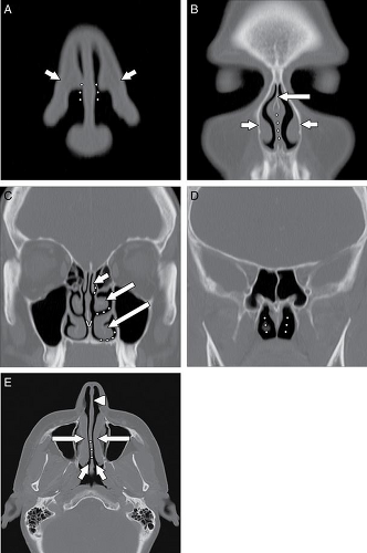 Figure 10.2 Normal nasal cavity anatomy. All the following images are CT images utilizing a bone algorithm in either an axial or coronal plane. Coronal CT image (A) demonstrates the nasal ala (arrows) and the nasal vestibule (dots). Coronal CT image (B) slightly more posterior to A demonstrates the perpendicular plate of the ethmoid (medium arrow), the cartilaginous portion of the nasal septum (dots), and the piriform aperture (small arrows). Coronal CT image (C) slightly more posterior to B demonstrates the superior (small arrow), middle (medium arrow), and inferior (large arrow) turbinates as well as the vomer (V). The superior, middle, and inferior meati are located below their respective turbinates (small dots). Coronal CT image (D) slightly more posterior to C demonstrates the nasal choana (dots). Axial image (E) at the level of the inferior turbinates (large arrows) demonstrates the cartilaginous portion of the nasal septum (arrowhead), the vomer (dots), and the nasal choana (medium arrows). |
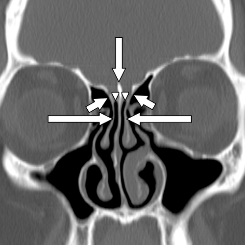 Figure 10.3 Basal lamella and cribriform plate. Coronal reformatted CT image with a bone algorithm through the anterior skull base demonstrates the basal lamella as a cephalad extension of the middle turbinates (large arrows). The basal lamella attach to the lateral lamella of the cribriform plate (small arrows). The medial lamella (arrowheads) of the cribriform plate and the crista galli (medium arrow) are also shown. |
The ostiomeatal complex (OMC) comprises the primary functional drainage unit for the maxillary sinuses, the frontal sinuses, and the anterior ethmoid air cells. This region has several components including the natural maxillary sinus ostium (internal maxillary os), infundibulum, uncinate process, ethmoid bulla, hiatus semilunaris, and the middle meatus (Fig. 10.1) (5).
Mucus secretions, trapped dust particles, and inflammatory cells in the maxillary sinus are propelled centripetally by pseudostratified columnar ciliated epithelium (5,6). The cilia beat 250 to 300 times per minute in a synchronous manner (6), directed supero-medially toward the natural ostium of the antrum (Fig. 10.4). Because of this phenomenon, FESS is most often performed to expand this ostium and the remainder of the OMC. Indeed, any surgery neglecting the natural ostium in the setting of an OMC obstruction will most often fail in adequately treating the patient. This was seen years ago in patients who received a Caldwell-Luc procedure ( Fig. 10.5), in which a nasal antral window was created along the inferior aspect of the maxillary antrum; this did not address the OMC and was prone to failure. Extending superiorly from the maxillary sinus ostium is an aerated channel termed the infundibulum, which is bordered by the infero-medial orbital wall laterally and by the uncinate process medially. The
uncinate process is a thin osseous plate that arises as a cephalad extension from the lateral wall of the nasal cavity behind the nasolacrimal fossa (Fig. 10.1). Secretions passing through the infundibulum reach the hiatus semilunaris, which is a region located below the ethmoid bulla (the largest antero-inferior ethmoid air cell) and above the uncinate process (4,5,7). This in turn opens into the middle meatus inferiorly. Secretions from the middle meatus drain into the nasal cavity, posteriorly through the nasal choanae, and into the nasopharynx (1,2). Eventually, the secretions are swallowed.
uncinate process is a thin osseous plate that arises as a cephalad extension from the lateral wall of the nasal cavity behind the nasolacrimal fossa (Fig. 10.1). Secretions passing through the infundibulum reach the hiatus semilunaris, which is a region located below the ethmoid bulla (the largest antero-inferior ethmoid air cell) and above the uncinate process (4,5,7). This in turn opens into the middle meatus inferiorly. Secretions from the middle meatus drain into the nasal cavity, posteriorly through the nasal choanae, and into the nasopharynx (1,2). Eventually, the secretions are swallowed.
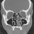
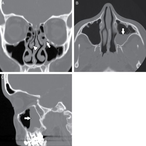 Figure 10.4 Opacified osteomeatal complex. Coronal reformatted CT image (A) demonstrates opacification of the left infundibulum (arrow) and left middle meatus (dots). A paradoxical right middle turbinate is incidentally noted (arrowhead). Axial (B) and sagittal reformatted (C) CT images in the same patient demonstrate a moderate sized air fluid level layering dependently in the left maxillary sinus (arrow). |
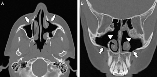 Figure 10.5 Caldwell-Luc procedure. Axial (A) and direct coronal (B) CT images with a bone algorithm demonstrate surgical defects in the anterior wall of the maxillary sinuses (arrows) and large nasoantral windows (arrowheads, B). Caldwell-Luc procedures are no longer commonly performed to treat sinus inflammatory disease. Functional endoscopic sinus surgery (FESS) is not the treatment of choice to treat sinus inflammatory disease. |
The superior meatus is the region lateral to the superior turbinate. It receives secretions from the posterior ethmoid cells and the sphenoid sinus. The outflow tract between the sphenoid sinus and the posterior ethmoids is termed the sphenoethmoidal recess (Fig. 10.2). This distinct functional unit is sometimes called the posterior ostiomeatal complex. The inferior meatus, which lies lateral to the inferior turbinate, does not serve as a drainage passageway for sinus secretions, but rather receives tears draining from the nasolacrimal sac and duct (1–3).
The frontal sinus outflow tract is a third functional unit and comprises the lower frontal sinus, the frontal ostium, and the frontoethmoidal recess (7). The frontal sinus outflow tract has an hourglass configuration on sagittal reformatted images. As the frontal sinus tapers inferiorly, it forms the frontal ostium, which is the narrowest portion of this hourglass configuration (7). Just inferior to the frontal ostium is the frontoethmoidal (or frontal) recess, which typically drains into the anterior ethmoids and then the middle meatus via anterior ethmoid ostia. Alternatively, the frontoethmoidal recess may directly drain into the middle meatus.
Anatomic Variants
Earwaker (8) analyzed the computerized tomography (CT) scans of 800 patients who were referred for evaluation prior to FESS. He found that only 57 of these 800 patients did not have anatomic variants. Of the described 52 types of anatomic variants, 93% of the patients had one or more variants. While these variants are frequently of no clinical significance, in some circumstances they may predispose to obstruction of the normal pathways of mucus drainage, or they may serve to increase the risk of complications associated with FESS. Consequently, familiarity with some of the more common variants is important.
Several variations in the anatomy of the nasal cavity can result in narrowing of the nasal cavity and obstruction to the drainage of the ipsilateral maxillary sinus and ethmoid air cells. For example, the nasal septum may be severely deviated toward one side (Fig. 10.6), narrowing the nasal cavity. Similarly, a bony nasal septal spur, with or without nasal septal deviation, may compromise the OMC and nasal cavity.
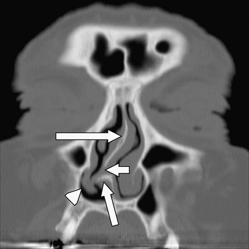 Figure 10.6 Nasoseptal deviation. Coronal reformatted CT image with a bone algorithm demonstrates marked deviation of the nasal septum with the vomer deviated to the right (small arrow) and the perpendicular plate of the ethmoid (large arrow) deviated to the left. A superimposed spur (medium arrow) is associated with deformity of the right inferior turbinate (arrowhead). |
A concha bullosa (Fig. 10.7) is an aerated turbinate head, most commonly associated with the middle turbinate, although aeration can also be seen in the superior and inferior turbinate heads (5). Various studies use different degrees of pneumatization to define a concha bullosa; consequently, the reported prevalence ranges from 4% to 80% (9). There is a strong relationship between the presence of a concha bullosa and contralateral nasal septal deviation although Stallman et al. (10) found no significant increase in paranasal sinus disease associated with a concha bullosa. Concha bullosa are lined by secretory mucoperiosteum and are therefore prone to the same sinus disease processes as other air cells (2).
Normally, middle turbinates are convex medially. A paradoxical middle turbinate (Fig. 10.4 and Fig. 10.8) refers to a middle turbinate that is convex laterally. This is a common variant and is most often an incidental finding. Rarely, the middle meatus may be narrowed by a paradoxical middle turbinate and this narrowing can predispose to sinus obstruction when associated with mucosal inflammation or edema. Occasionally, paradoxical middle turbinates may make surgical access to the OMC difficult (7). The uncinate process can have varying appearances. The orientation of the uncinate process may be vertical, horizontal (particularly in conjunction with a large ethmoid bulla) or anywhere in between (8,11). The uncinate process may also be pneumatized and expanded, resulting in compromise to the infundibulum.
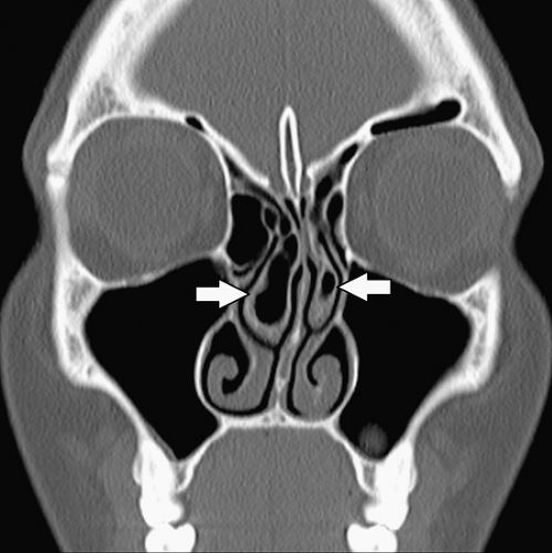 Figure 10.7 Concha bullosa. Coronal reformatted CT image with a bone algorithm through the mid nasal cavity demonstrates bilateral concha bullosa involving the middle turbinates, right larger than left (arrows). |
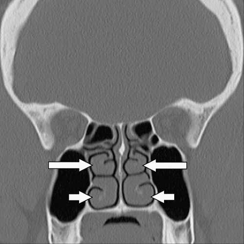 Figure 10.8 Paradoxical middle turbinates. Coronal reformatted CT image demonstrates bilateral paradoxical middle turbinates (medium arrows). The heads of these middle turbinates curve inward rather than outward as opposed to the inferior turbinates (small arrows). |
A deviated nasal septum and an associated osseous spur often contact and deform the adjacent turbinates. Since the nose and paranasal sinuses are innervated by the first and second divisions of the trigeminal nerve (12), the potential exists for “contact point” headaches. These contact point headaches are referred headaches from stimulation of the trigeminal nerve and can significantly improve following surgical removal of the spur and a septoplasty (13,14). However, the presence or severity of a contact point between a septal deviation/spur and a turbinate is not a primary indication for surgery (13). Careful history, physical exam, and other potential causes for the patient’s headaches should be considered prior to surgery.
Many common variants arise from the ethmoid air cells and extend into the adjacent sinuses or outflow tracts. These are collectively termed extramural ethmoid air cells (7). One of the more common variants is the Haller cell (Fig. 10.1 and Fig. 10.9). The Haller cell is an air cell that lies within the superomedial maxillary antrum and along the inferior medial margin of the orbit (Fig. 10.4). A large Haller cell may narrow the maxillary sinus ostium or the infundibulum, depending on its specific position along the sinus margin. Agger
nasi cells ( Fig. 10.10) are extremely common and are the most anterior ethmoidal air cells, located just ventral to the nasolacrimal canal. These cells are in, or adjacent to, the lacrimal bones and may anatomically narrow the frontoethmoidal recess (7). Agger nasi cells are important surgical landmarks for the position of the frontoethmoidal recess. A frontal bulla ( Fig. 10.11) is an ethmoid air cell that extends along the back wall of the frontoethmoidal recess into the frontal sinus, occasionally resulting in obstruction of the frontal sinus and/or frontoethmoidal recess (15). Onodi cells (Fig. 10.12) are posterior ethmoid air cells that share a common wall with the optic canal and typically lie above the sphenoid sinus. The significance of the Onodi cell relative to surgery is discussed below.
nasi cells ( Fig. 10.10) are extremely common and are the most anterior ethmoidal air cells, located just ventral to the nasolacrimal canal. These cells are in, or adjacent to, the lacrimal bones and may anatomically narrow the frontoethmoidal recess (7). Agger nasi cells are important surgical landmarks for the position of the frontoethmoidal recess. A frontal bulla ( Fig. 10.11) is an ethmoid air cell that extends along the back wall of the frontoethmoidal recess into the frontal sinus, occasionally resulting in obstruction of the frontal sinus and/or frontoethmoidal recess (15). Onodi cells (Fig. 10.12) are posterior ethmoid air cells that share a common wall with the optic canal and typically lie above the sphenoid sinus. The significance of the Onodi cell relative to surgery is discussed below.
 Figure 10.9 Haller cell. Coronal CT image demonstrates a moderate-sized Haller cell (medium arrow) that forms the lateral margin of the left infundibulum (small arrows). Haller cells can result in narrowing or obstruction of an infundibulum. In this case, the left infundibulum is narrowed by the Haller cell and opacified due to superimposed mucosal thickening. |
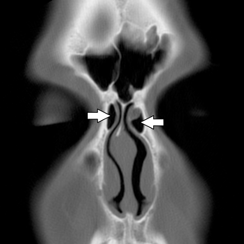 Figure 10.10 Agger Nasi cells. Direct coronal image with a bone algorithm demonstrates paired Agger Nasi cells (arrow), with the one on the patient’s left containing mild mucosal thickening (small arrows). |
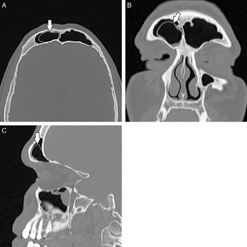 Figure 10.11 Frontal bulla. Axial CT image with a bone algorithm (A) demonstrates an additional air cell within the right frontal sinus (arrow) consistent with a frontal bulla. A frontal bulla can result in obstruction of the ipsilateral frontal sinus by obstruction of the frontoethmoidal recess although the frontal sinus in this patient is relatively clear at the time of scanning. Coronal (B) and sagittal (C) reformatted images in a bone algorithm also demonstrate the frontal bulla (arrow). |
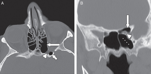 Figure 10.12 Onodi cell. Axial (A) and coronal (B) CT images with a bone algorithm demonstrate a posterior most left ethmoid air cell (Onodi cell) (medium arrow) forming a margin with the left optic canal (arrowhead). The Onodi cell extends into and pneumatizes the left anterior clinoid process (small arrow). The typical location for an Onodi cell is superior to the sphenoid sinus (dots), as the coronal image demonstrates. |
Complications of Functional Endoscopic Sinus Sugery—Anatomic Considerations
The anatomy of the nasal cavity and ethmoid labyrinth is extremely complex and variable. Endoscopy provides a two-dimensional view of three-dimensional anatomy. Conventional cross sectional imaging, and more recently intraoperative framed and frameless stereotactic guided imaging techniques, can help avoid complications from endoscopic sinus surgery.
When surgical complications do occur, CT and magnetic resonance imaging (MRI) are essential for evaluation. A common site prone to complications is the lamina papyracea (the medial orbital wall), which
may be breached during ethmoid surgery. The surgeon should be aware of any preexisting lamina papyracea deformities to avoid inadvertent breach of the orbit.
may be breached during ethmoid surgery. The surgeon should be aware of any preexisting lamina papyracea deformities to avoid inadvertent breach of the orbit.
Variations in the degree of pneumatization of the sphenoid sinus can also result in surgical mishap. The internal carotid artery runs lateral to the sphenoid sinus wall, and if medially positioned, may bulge into the sphenoid sinus lumen, with the possibility of injury during sinus surgery; this may lead to serious hemorrhage or pseudoaneurysm formation ( Fig. 10.13).
Pneumatization of the sphenoid sinus can extend into the anterior clinoid processes. The anterior clinoid processes (and the optic struts) normally form the lateral wall of the optic canal. Clinoid pneumatization can therefore expose the optic nerve to surgical damage during sphenoid sinus surgery. Oftentimes the sphenoid septum attaches to one of the carotid canals. If this is present, the potential exists for a fracture to the carotid canal on resection of the sphenoid septum. As discussed above, Onodi cells (Fig. 10.12) are posterior ethmoid air cells that share a common wall with the optic canal. If a surgeon is unaware of the presence of an Onodi cell, the surgeon could inadvertently breach the optic canal and damage the optic nerve. The presence and exact location of an Onodi cell can only be defined prior to surgery with cross sectional imaging, ideally with CT.
Pneumatization of the sphenoid sinus can extend into the anterior clinoid processes. The anterior clinoid processes (and the optic struts) normally form the lateral wall of the optic canal. Clinoid pneumatization can therefore expose the optic nerve to surgical damage during sphenoid sinus surgery. Oftentimes the sphenoid septum attaches to one of the carotid canals. If this is present, the potential exists for a fracture to the carotid canal on resection of the sphenoid septum. As discussed above, Onodi cells (Fig. 10.12) are posterior ethmoid air cells that share a common wall with the optic canal. If a surgeon is unaware of the presence of an Onodi cell, the surgeon could inadvertently breach the optic canal and damage the optic nerve. The presence and exact location of an Onodi cell can only be defined prior to surgery with cross sectional imaging, ideally with CT.
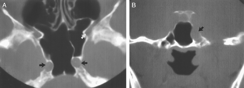 Figure 10.13 Carotid canals. Axial (A) and coronal (B) computed tomography images demonstrate medial bulging of the internal carotid arteries (black arrows) into the sphenoid sinus; the arteries are susceptible to injury during surgery in this location. The superior orbital fissure is again seen (white arrow). |
The roof of the ethmoid sinus is formed by the frontal bone (16). An asymmetric low-lying ethmoid roof increases the chances of inadvertent breech by the unsuspecting surgeon and may result in herniation of the brain and/or meninges. The cribriform plate lies at the midline between the roofs of the ethmoids. The cribriform plate contains a medial and a lateral lamella ( Fig. 10.3 ). The lateral lamella is an extremely thin osseous structure and is a point of structural weakness in the anterior skull base (7,17). The anterior ethmoidal artery enters the intracranial compartment through the lateral lamella of the cribriform plate. If the lateral lamella is breached, the anterior ethmoidal artery may be damaged with risk of intracranial hemorrhage (2,5,8,18) or arteriovenous fistula formation. The anterior ethmoidal artery also traverses within the orbit, lateral to a notch located along the superomedial margin of the orbit. This notch serves as a surgical landmark to the location of the anterior ethmoidal artery. The anterior ethmoidal artery exits the orbit via the anterior ethmoidal foramen (7). Occasionally, the anterior ethmoidal artery traverses within a small canal that crosses the ethmoid air cells as it ascends intracranially; if this small canal is surgically breached, the anterior ethmoidal artery can retract into the orbit resulting in uncontrolled intraorbital hemorrhage, increased intraorbital pressure, and possibly blindness from retinal artery occlusion (5). Operative injuries to the orbital walls, cribriform plate, and ethmoid roofs may be best seen on coronal CT (Fig. 10.14), but the resulting complications of cerebritis, meningitis, empyema, or abscess are best demonstrated on contrast-enhanced MR (18,19).
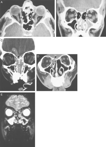 Figure 10.14 Surgical complications. Axial (A) and coronal (B) computed tomography (CT) images from a patient who experienced left medial rectus palsy following sinus surgery. There has been inadvertent resection of the left medial orbital wall (black arrows). The left medial rectus muscle is seen herniating through the defect (white arrowhead) into the adjacent ethmoid air cell. The normal position of the medial rectus muscle is seen on the right (R). A coronal CT (C) from a different patient demonstrates an intracranial hemorrhage (B) as a result of injury to the fovea ethmoidalis (black arrow). Blood (b) is also filling the sinus and nasal cavities. A coronal CT (D) from another postoperative patient who suffered a similar injury shows abnormal soft tissue density (curved white arrow) adjacent to an apparent discontinuity of the bony fovea ethmoidalis and cribriform plate (black arrow). A coronal T2-weighted magnetic resonance image (E) illustrates this soft tissue density to be brain parenchyma herniating through the bone defect (white arrows). This is called a postoperative encephalocele. |
CSF leak is another known complication of FESS. The CSF leak in this population of patients is usually located in the region of the roof of ethmoids or cribriform plate. Patients may present with CSF rhinorrhea, recurrent meningitis, and meningoencephalocele. Symptoms may occur immediately or be delayed up to 2 years after the operative procedure (5,11). A radionuclide cisternogram can be performed to confirm the presence of a leak, but this test provides only limited anatomic information concerning the exact location of the leak. A noncontrast CT can be performed in the axial and coronal planes to localize a fracture and has been shown to demonstrate the site of a CSF fistula 71% of the time (20). A CT cisternogram is a procedure
whereby contrast is placed into the subarachnoid space (via a lumbar puncture) and a CT is performed with direct coronal images (Fig. 10.15). The coronal images are ideally obtained with the patient placed prone and with the neck extended to promote leakage of contrast through the defect. The reported sensitivity of CT cisternography to detect CSF leaks (of all causes) is 36% to 81%. Although CT cisternography can aid in anatomical localization of the site of a leak, the sensitivity is diminished if the patient is not actively leaking CSF at the time of the exam (21). If a patient is leaking CSF, a β2-transferrin can be sent for laboratory analysis to verify that there is a CSF leak. Some authors advocate the use of MRI with or without intrathecal gadolinium contrast to localize the site of a CSF leak ( 20) ( Fig. 10.16 ). T2-weighted images provide excellent contrast between the CSF and bone/air interface. Continuity of high T2 signal CSF from the intracranial subarachnoid space through an osseous defect into extracranial sites can sometimes be identified (22). However, a potential drawback to MRI cisternography is that the CSF and gadolinium may be obscured by fluid and enhancing mucosal thickening in the sinuses, respectively. Additionally, CT provides superior bone detail compared to MRI (21). Currently, most practitioners perform either a noncontrast CT with or without a β2-transferrin assay, or CT cisternography.
whereby contrast is placed into the subarachnoid space (via a lumbar puncture) and a CT is performed with direct coronal images (Fig. 10.15). The coronal images are ideally obtained with the patient placed prone and with the neck extended to promote leakage of contrast through the defect. The reported sensitivity of CT cisternography to detect CSF leaks (of all causes) is 36% to 81%. Although CT cisternography can aid in anatomical localization of the site of a leak, the sensitivity is diminished if the patient is not actively leaking CSF at the time of the exam (21). If a patient is leaking CSF, a β2-transferrin can be sent for laboratory analysis to verify that there is a CSF leak. Some authors advocate the use of MRI with or without intrathecal gadolinium contrast to localize the site of a CSF leak ( 20) ( Fig. 10.16 ). T2-weighted images provide excellent contrast between the CSF and bone/air interface. Continuity of high T2 signal CSF from the intracranial subarachnoid space through an osseous defect into extracranial sites can sometimes be identified (22). However, a potential drawback to MRI cisternography is that the CSF and gadolinium may be obscured by fluid and enhancing mucosal thickening in the sinuses, respectively. Additionally, CT provides superior bone detail compared to MRI (21). Currently, most practitioners perform either a noncontrast CT with or without a β2-transferrin assay, or CT cisternography.
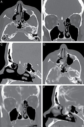 Figure 10.15 Encephalocele. Axial (A), coronal reformatted (B), and sagittal reformatted (C) noncontrast CT images through the sinuses with a bone algorithm demonstrate a relatively large osseous defect involving the roof of the right ethmoid including the right lateral lamella (arrow, B). A nonspecific opacity is present in the posterior ethmoid suggestive of a cephalocele (dots). Axial (D), coronal reformatted (E), and sagittal reformatted (F) CT images through the sinuses with a bone algorithm following intrathecal administration of contrast demonstrate contrast extending into the lesion within the right posterior ethmoids. The partial opacification of the lesion with contrast (arrow) confirm that the lesion is partially CSF and partially brain tissue. This is consistent with an encephalocele. |
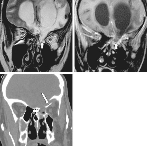 Figure 10.16 Ethmoidal meningocele following trauma. Coronal T2-weighted image (A) demonstrates a defect at the roof of the left ethmoid with meninges and CSF extending through the defect consistent with a meningocele. Coronal T1-post contrast image (B) and coronal reformatted CT image (C) with a bone algorithm also demonstrate the same finding (small arrow). A fracture of the roof of the left orbit is seen on the CT image (medium arrow). |
Empty nose syndrome (Fig. 10.17) refers to the sensation of nasal congestion that occurs from an atrophic rhinitis or following resection of the inferior turbinate, middle turbinate, or both (23). The function of the turbinates is to filtrate, warm, and humidify inhaled air. Absence of the nasal turbinates due to surgery results in alteration of air flow and a deficient nasal sensation. However, the patient paradoxically experiences a congested nasal sensation despite a widely patent nasal cavity (23). The empty nose syndrome is considered rare (23), although this entity is likely directly proportional to the extent of the turbinate resection performed during surgery.
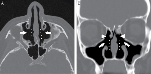 Figure 10.17 Empty nose syndrome. Axial (A) and coronal (B) CT images with a bone algorithm demonstrate absent turbinates (dots), uncinectomies with antrostosmies (small arrows) and ethmoidectomies (arrowheads). This patient had symptoms of chronic sinusitis. Turbinates humidify inhaled air. The lack of the turbinates results in a congested sensation for the patient. |
Imaging Technique
Related posts:
Stay updated, free articles. Join our Telegram channel

Full access? Get Clinical Tree


