Techniques and Positioning in Mammography
During the past three decades, there has been significant improvement in the equipment and image-recording systems for mammography. In addition to providing better images, these developments have resulted in a significant reduction in radiation dose. Mammography has evolved from more dedicated equipment and industrial film, through xeromammography, dedicated film-screen mammography, and now to full-field digital mammography (Fig. 2.1). With the importance of an emphasis on mammography in the role of early detection of breast cancer, it is of utmost importance that meticulous techniques be used. Factors that affect the image quality include equipment, image-recording system, processing, compression of the breast, and the technologist’s skill in positioning the patient. Adherence to strict quality assurance guidelines is critical in mammography to maintain optimum image quality (1,2). The Mammography Quality Standards Act (MQSA) (3) was passed in 1992 and regulates mammography facilities in the United States. The entire mammography process is addressed through MQSA, but importantly, the quality of images is carefully evaluated.
The interpretation skills of the radiologist are limited by a suboptimal image. A poor-quality mammogram or poor positioning can account for many of the cancers missed by mammography (4,5), and technical errors should not be overlooked or accepted. For the radiologist to detect subtle signs of malignancy, high-quality images are a must. The emphasis of this book is on interpretation and pattern recognition, but it is important to review briefly the technical factors that affect the mammographic image.
Equipment
Only dedicated units should be used for film-screen mammography. Dedicated units are those with special focal spots, target and filter materials, low kilovoltage, and compression devices designed to optimize the mammographic image at low radiation doses. Under no circumstances can nondedicated equipment produce images of similar quality to those performed with dedicated units.
There are three types of target materials used for mammography: molybdenum, rhodium, and tungsten. With molybdenum targets, 0.3-mm molybdenum filtration is used; the molybdenum targets are particularly well suited for mammography because of the low kiloelectron volt x-rays produced. The characteristic peaks for molybdenum are 17.9 and 19.5 keV, which provide high-contrast images for breasts of average thickness.
When the 0.3-mm molybdenum filter is used, the photons at energies greater than 20 keV are suppressed, and a larger number of low-energy photons are used in recording the images (6). The kilovolt peak (kVp) setting for molybdenum targets is generally at 25-28 kVp (6).
Alternative target/filter combinations for mammography include molybdenum/rhodium, rhodium/rhodium, and tungsten/rhodium. With tungsten targets, a beryllium window and minimal aluminum filtration are recommended. In comparison with a molybdenum target, even at low kVp settings, the tungsten target produces more high-energy photons, and the subject contrast is, therefore, lower (Fig. 2.2). Generally, settings of 22–26 kVp should be used for tungsten targets (A) (6,7,8). For most patients, a molybdenum target and a 0.06-mm molybdenum filter is automatically in place at low kVp settings; to penetrate thick dense breasts, the 0.05-mm rhodium filter is used at higher kVp settings (2).
Resolution is affected by the recording system’s unsharpness, geometric unsharpness, and motion (9). The size of the focal spot of the tube is of particular importance in mammography because of the high resolution required for this work. To reduce geometric blurring, the focal spot
size and the distance between the breast and image receptor should be kept as small as possible, and the object-to-focal-spot distance should be maximized (10). The size of the focal spot becomes even more important in magnification mammography (6), where it is generally recommended that the measured focal-spot size be no greater than 0.3 mm (11) and preferably in the range of 0.1 to 0.2 mm (12,13).
size and the distance between the breast and image receptor should be kept as small as possible, and the object-to-focal-spot distance should be maximized (10). The size of the focal spot becomes even more important in magnification mammography (6), where it is generally recommended that the measured focal-spot size be no greater than 0.3 mm (11) and preferably in the range of 0.1 to 0.2 mm (12,13).
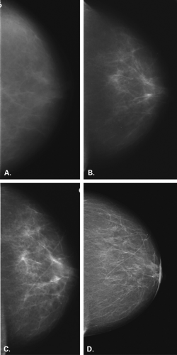 Figure 2.1 HISTORY: Series of screening mammograms over 22 years. MAMMOGRAPHY: Right CC view in 1985 (A), 1987 (B), 1996 (C), and 2006 (D) performed with the following equipment and techniques: A: Dedicated unit with a tungsten target, aluminum filter, and no grid. B: Dedicated unit with molybdenum target and filter and a grid. C: Dedicated unit with molybdenum target/filter, grid, and a newer film-screen combination with extended processing showing contrast improvement. D: Full-field digital unit with a tungsten/rhodium target/filter and a selenium detector showing excellent contrast and visibility of structures. |
The use of grids in mammography improves image quality by reducing scatter, thus increasing contrast; there is a concomitant increase in radiation dose to the patient (14). Grids are of particular advantage in imaging the more dense, thick breast, in which more scattered radiation is present (15). However, because of the improvement in image quality with a grid, all routine mammography is performed with a grid. Mammography units have reciprocating grids with a ratio of approximately 5:1 (6). The grids used in mammography are thinner than conventional grids and contain carbon fiber interspace material for lower absorption. Typical reciprocating grids are composed of 16-μm lead strips separated by 300-μm carbon-fiber resin interspaces (7). The increase in the radiation dose with a grid is about two times that of a nongrid film, but this may be compensated for by using faster screen-film combinations. Grids are not utilized for magnification mammography because of the increased dose and length of exposure.
Dedicated mammography units should be equipped with a firm radiolucent compression device that forms a 90-degree angle with the chest wall. No rounded or curved edge compression devices should be used because the posterior aspect of the breast will not be adequately visualized (16). Proper compression of the breasts during mammography is extremely important in terms of producing an image of satisfactory diagnostic quality. Compression of the breasts is a very important factor in reducing scatter radiation, which degrades the image. With compression, there is spreading of the tissues apart, and small lesions are more easily identified within the parenchyma. The immobilization of the breasts decreases motion blurring, and the location of structures in the breast closer to the film receptor decreases geometric blurring. There is less variation in the density of the areas of breast with compression to a uniform thickness from nipple to chest wall. Importantly, the radiation dose to the breast is decreased with compression (7).
Image Recording System
It is important that a film-screen system specifically designed for analog mammography be utilized in order to
obtain the proper diagnostic quality of the images. With dedicated units and the common use of grids and magnification techniques, it is also important that the film-screen combination chosen have the lowest radiation dose while the quality of the images is maintained. Single-emulsion film is recommended for contact mammography because of the image degradation secondary to crossover in double-emulsion systems. In 1972, DuPont introduced the LoDose screen-film systems, which was followed by the DuPont LoDose 2 system. Kodak introduced the MinR system in 1976 and OM film in 1980. Since then, numerous film-screen combinations have been designed specifically for mammography. Some of these films have been specifically developed to be used in either standard 90-second or the extended 3-minute processors. The screens used for most routine mammography are single-back screens. The film and screen are in intimate contact, with the emulsion in contact with the top of the screen (17). Mammographic film-screen combinations have a much higher resolution than that of conventional radiography systems (2). Kimme-Smith et al. (17) found that the screens are of primary importance for good resolution, whereas contrast is affected more by type of film and processing (2,17).
obtain the proper diagnostic quality of the images. With dedicated units and the common use of grids and magnification techniques, it is also important that the film-screen combination chosen have the lowest radiation dose while the quality of the images is maintained. Single-emulsion film is recommended for contact mammography because of the image degradation secondary to crossover in double-emulsion systems. In 1972, DuPont introduced the LoDose screen-film systems, which was followed by the DuPont LoDose 2 system. Kodak introduced the MinR system in 1976 and OM film in 1980. Since then, numerous film-screen combinations have been designed specifically for mammography. Some of these films have been specifically developed to be used in either standard 90-second or the extended 3-minute processors. The screens used for most routine mammography are single-back screens. The film and screen are in intimate contact, with the emulsion in contact with the top of the screen (17). Mammographic film-screen combinations have a much higher resolution than that of conventional radiography systems (2). Kimme-Smith et al. (17) found that the screens are of primary importance for good resolution, whereas contrast is affected more by type of film and processing (2,17).
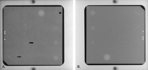 Figure 2.2 Digital images of the American College of Radiology Accreditation phantom demonstrating the effect of target/filter combination on contrast. A was obtained using molybdenum/molybdenum target filter at 28 kVp and 97 mAs. B was obtained using tungsten/rhodium target/filter at 28 kVp and 83 mAs. The contrast is higher on the Mo/Mo image (A), and more objects are clearly visible (arrows). |
Cassettes specifically designed for mammography are most commonly used, but polyethylene envelopes that are vacuum sealed have also been used. The cassette and its screen should be dusted daily to maintain proper quality control and to reduce dust artifacts. Weekly, wet cleaning of the screen is necessary to optimize image quality in reducing artifacts.
Quality control of film processing is of great importance in mammography. It is important to follow the manufacturer’s recommendation for film processing in terms of the chemicals used, replenishment rate, development time and temperature. Using a temperature that is lower than that recommended by the manufacturer for mammography causes a loss in film speed and contrast (2), thereby necessitating a higher dose to produce films of satisfactory optical density (18). Many facilities have used extended-cycle processing for single-emulsion films (2,19,20). With extended-cycle processing, the film spends more time in the developer, thereby increasing the total processing time to 3 minutes. It is important that the processor be dedicated to mammography if extended-cycle processing is used. A reduction in radiation dose by 30% (2,19) and an increase (19) in contrast of 11% were found when Kodak OM1-SO177 film was tested in 3-minute rather than 90-second processing. Kimme-Smith et al. (21) found that extended cycle processing increased noise and decreased dose, but diagnostic capabilities were not compromised. More recently, newer films and screens have been developed that provide the higher contrast and lower dose afforded by extended cycle processing, yet the processing time for these films is 90 seconds.
Image Contrast
Contrast is dependent on subject contrast (radiation quality and kVp), film contrast, film processing (darkroom, chemistry, development time and temperature), and scattered radiation (compression, grid) (22). There are a number of factors in the darkroom that affect radiographic contrast. The film should be processed according to the manufacturer’s recommendations. The purity of the chemistry, the replenishment rate of the chemicals, and the temperature all affect the contrast. The time for processing also affects contrast significantly. Extended cycle processing has been used for mammography to increase the contrast of the images.
Another major effect on contrast is scattered radiation. The use of grids in mammography reduces scatter and increases contrast. The grid attenuates the primary radiation, though, and the dose is increased about twofold (23).
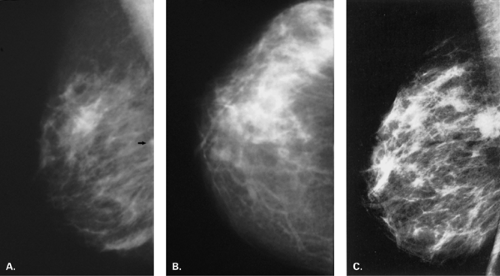 Figure 2.3 HISTORY: A 50-year-old woman with a lump deep in the left breast. MAMMOGRAPHY: Left ML (A), CC (B), and MLO (C) views. No abnormalities are seen on the CC view, but on the ML view a questionable density (arrow) is seen positively. However, on the MLO view, there is a high-density nodular mass deep in the breast near the chest wall. This emphasizes the importance of performing the MLO view routinely in order to visualize the posterior aspects of the breast adequately. IMPRESSION: Carcinoma. HISTOPATHOLOGY: Infiltrating ductal carcinoma. |
Radiation Dose
The parenchyma of the breast, not the skin, is the area that is of greater concern regarding exposure. Therefore, the absorbed glandular dose, not the skin entrance dose, is the more important measurement (6). For a 5-cm-thick average breast, the mean absorbed dose using OM film at 28 kVp with a molybdenum target is approximately 0.05 rad (6). Factors that affect radiation dose include breast-tissue composition and thickness, x-ray tube target materials, filtration, kVp, grid use, film-screen combination, and processing (2). With the development of dedicated mammography equipment and the improvement in
film-screen systems, there has been a tremendous decrease in the radiation dose from mammography over the last decades.
film-screen systems, there has been a tremendous decrease in the radiation dose from mammography over the last decades.
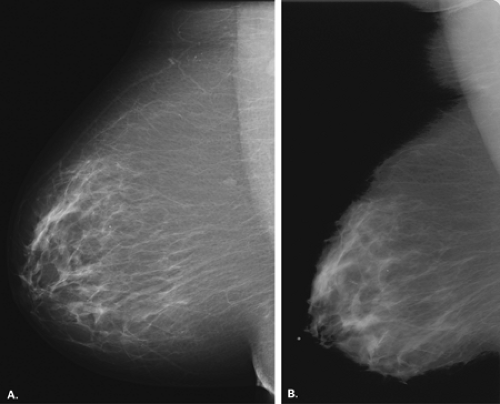 Figure 2.4 HISTORY: Screening mammogram with prior films for comparison on a difficult-to-position patient because of her size. MAMMOGRAPHY: Current left MLO (A) view performed with a full-field digital unit shows the breast to be well positioned, especially for the large size. The pectoralis major muscle is visualized down to the level of the nipple. There is however, some overlap of the upper abdomen at the inframammary fold. A normal lymph node is noted in the axillary tail. Comparison with the prior study (B) shows that significantly more breast tissue has been included on the current study. The muscle, the node, and several centimeters of posterior breast tissue are visible on the well-positioned MLO versus the prior study. IMPRESSION: Normal left mammogram with better positioning on the current MLO view. |
Digital Mammography
Because of the resolution requirements for mammography, the technical developments to achieve full-field imaging have been challenging. Yet, full-field digital mammography has been developed and tested, and is clinically available. Other than the diagnostic improvements with digital compared with analog or film-screen mammography, as shown in the Digital Mammographic Imaging Screening Trial (DMIST) (24), there are distinct technical improvements as well.
With film-screen mammography, the various functions related to imaging are accomplished on a piece of film:
image acquisition, interpretation, and storage. With digital mammography, these three functions are separated, and each is optimized. The large dynamic range and improved contrast overcome some of the limitations of film-screen mammography. The dynamic range of digital mammography is approximately 1,600:1 versus 100:1 for film (25). The digital mammogram is particularly helpful because of increased contrast resolution in dense breast tissue.
image acquisition, interpretation, and storage. With digital mammography, these three functions are separated, and each is optimized. The large dynamic range and improved contrast overcome some of the limitations of film-screen mammography. The dynamic range of digital mammography is approximately 1,600:1 versus 100:1 for film (25). The digital mammogram is particularly helpful because of increased contrast resolution in dense breast tissue.
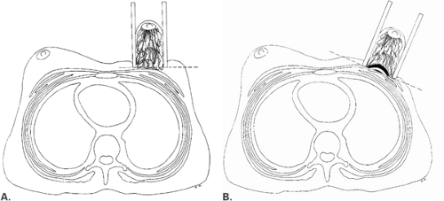 Figure 2.5 Cross sections through the thorax show that the axillary tail of the breast may not be included on a ML projection (A), but on the MLO projection (B), the axillary tail and pectoralis major muscle are imaged. |
The spatial resolution of digital mammography is less than that of film, with the current units having a resolution of 50- to 100-μm pixel size. The line pair resolution of film mammography translates to an approximate pixel size of 25 μm. However, because of the other favorable factors with digital imaging, fine detail observation is not compromised (26).
Digital detector development has included several different technologies. An early unit was composed of multiple small detectors (charge-coupled devices) stitched together to create a larger detector. Another technology is slot scanning, in which a long narrow CCD is scanned along with the x-ray beam over the breast. The GE unit was the first unit approved by the Food and Drug Administration and has a flat panel detector composed an amorphous silicone photodiode array with a spatial resolution of 100 μm. More recently, Siemens and Hologic have developed and received approval for units that are based on direct digital image capture on an amorphous selenium plate.
Simultaneous development of computerized radiography has occurred for mammography. Photostimulable phosphor plates are exposed to x-rays and develop a latent image. The plates are scanned by a laser beam, and the images are printed onto film. Like digital mammography, the phosphor plates offer a higher dynamic range than film mammography (26).
Digital images may be interpreted as hard copy or soft copy. With hard-copy interpretation, the images are laser printed onto film. Soft-copy interpretation involves interpretation at a high-resolution workstation. Because of the amount of information in one image, the images are not displayed at full resolution on a 2 K ÷ 2 K workstation. The images are enlarged to full resolution and panned to see the entire breast, or the magnification tool is used. A distinct advantage of interpretation at the workstation is that the image may be postprocessed. Window leveling, zoom, and magnification are all useful tools to improve observations and analysis.
Another important advantage of digital imaging is improved archiving of the images. Instead of a large film room and the challenges of maintaining it, digital images are archived in a PACS (picture archiving and communication system) or in a local and remote server. Because of the communication aspects of digital imaging, telemammography is possible and allows for remote interpretation.
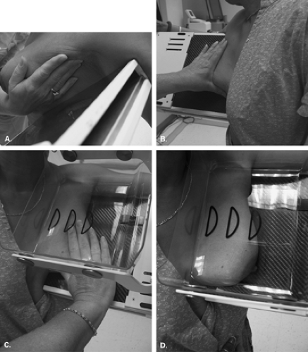 Figure 2.6 Steps in positioning the patient for the MLO view. A: The technologist determines the angle of the obliquity of the pectoralis major muscle by lifting the breast medially and turning the image receptor to this angle. B: The Bucky is turned to the angle of obliquity of the pectoralis major muscle (35 to 60 degrees). The breast is placed over the Bucky with the arm draped behind the receptor. The technologist maintains the breast in a up-and-out position as she moves the compression device into position. C: The inframammary fold is open, and the breast is elevated as the compression is applied. D: Final position shows the entire breast and low axilla in the field of view. |
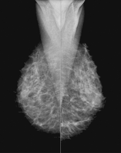 Figure 2.7 Well-positioned MLO views show the pectoralis major muscles bulging forward and visualized as a triangle with the apex at the level of the nipple. The nipple is elevated, and the inframammary fold region is open; the breast is well compressed. |
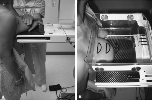 Figure 2.8 Positioning the patient for the CC view. (A) The technologist is using both hands to pull the breast forward over the receptor, and the receptor has been elevated to the elevated inframammary fold position. (B) On final positioning, the breast is pulled straight forward, and the medial aspect of the opposite breast is draped over the receptor. |
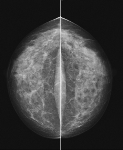 Figure 2.9 Well-positioned CC views show the breasts positioned straight forward and not rotated. The pectoralis major muscles are seen bilaterally. The nipple is in profile, and the breast is well compressed. |
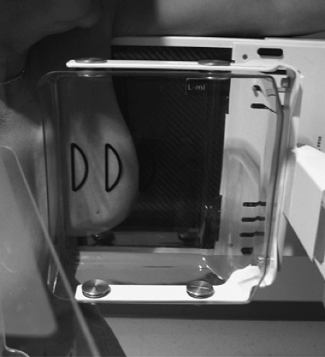 Figure 2.10 ML. Positioning the patient for the ML view. The breast is compressed from the medial aspect, and the degree of obliquity is 90 degrees. The axillary tail is not as included in the field of view as it is on the MLO view. |
Positioning
Most authors agree that two views should be performed for routine mammography (27,28). The craniocaudal (CC) view and the mediolateral oblique (MLO) view (29) are recommended as standard projections. Before the determination of the MLO projection, the views for mammography were a CC and a mediolateral (ML). With the advent of MLO positioning, more posterior tissue could be included in the field of view (Fig. 2.3). Additional views may be necessary to evaluate specific areas within the breast (30,31,32), and the techniques for positioning the patient for these various views are described in this chapter. For all views, it is of utmost importance that the breast be compressed properly.
Mediolateral Oblique View
When the patient is positioned properly, the MLO view will demonstrate the pectoralis major muscle and the entire breast, including the inferior portion and the axillary tail, on one film (Fig. 2.4). The concept of the MLO view is that the breast is compressed at the same angle of obliquity as the pectoralis major muscle transverses the chest wall. In compressing the muscle in this plane, the technologist is more able to pull the muscle forward over the cassette; therefore, the posterior breast tissue is also pulled forward (Fig. 2.5). The pectoralis major muscle has a triangular shape, with the apex at the level of the nipple. In general, the parenchyma should not extend to the posterior edge of the image on the MLO view. Instead, the parenchyma should be separated from the chest wall edge of the image by the retroglandular fat (33).
Related posts:

Stay updated, free articles. Join our Telegram channel

Full access? Get Clinical Tree


