Brachytherapy (brachy, from the Greek for “short distance”) consists of placing sealed radioactive sources close to, or in contact with, the target tissue.
Implantation techniques may be broadly characterized in terms of the following: surgical approach to the target volume (interstitial, intracavitary, transluminal, or mold techniques), means of controlling the dose delivered (temporary or permanent implants), source loading technology (preloaded, manually afterloaded, or remotely afterloaded), and dose rate (low, medium, or high).
Intracavitary insertion consists of positioning applicators containing radioactive sources into a body cavity in close proximity to the target tissue. The most widely used intracavitary treatment technique is insertion of a tandem and colpostats for cervical cancer.
All intracavitary implants are temporary; they are left in the patient for a specified time (usually 24 to 168 hours after source insertion for low-dose-rate [LDR] therapy) to deliver the prescribed dose.
Interstitial brachytherapy consists of surgically implanting small radioactive sources directly into the target tissues.
A permanent interstitial implant remains in place forever. The initial source strength is chosen so that the prescribed dose is fully delivered when the implanted radioactivity has decayed to a negligible level.
Surface-dose applications (sometimes called plesiocurie or mold therapy) consist of an applicator containing an array of radioactive sources, usually designed to deliver a uniform dose distribution to the intraoperative tumor bed, skin, or mucosal surface.
Transluminal brachytherapy consists of inserting a line source into a body lumen to treat its surface and adjacent tissues (10, 43).
Radiation exposure to nursing staff (and other hospital staff responsible for source loading and the care of implant patients) can be greatly reduced or eliminated by using remote afterloading devices, which consist of a pneumatically or motor-driven source transport system for robotically transferring radioactive material between a shielded safe and each treatment applicator (2).
According to International Commission on Radiation Units and Measurements (ICRU) Report No. 38 (5), LDR implants deliver doses at a rate of 40 to 200 cGy per hour (0.4 to 2.0 Gy per hour), requiring treatment times of 24 to 144 hours.
High-dose-rate (HDR) brachytherapy uses dose rates in excess of 0.2 Gy per minute (12 Gy per hour). Modern HDR remote afterloaders contain sources capable of delivering dose rates of 0.12 Gy per second (430 Gy per hour) at 1-cm distance, resulting in treatment times of a
few minutes. A heavily shielded vault and remote afterloading device are essential components of an HDR brachytherapy facility.
Temporary LDR implant patients must be confined to the hospital during treatment to manage the radiation safety hazard posed by the ambient exposure rates around the implant. HDR implants are usually performed as outpatient procedures.
Although not recognized by ICRU Report No. 38, the ultralow-dose-rate range (0.01 to 0.30 Gy per hour) is important; it is the dose rate used for permanent iodine-125 (125I) and palladium-103 (103Pd) seed implants.
The clinical utility of any radionuclide depends on physical properties such as half-life, radiation output per unit activity, specific activity (Ci per g), and photon energy. Detailed properties of radionuclides are listed in Table 6-1.
The traditional implant systems (Manchester, Quimby, and Paris) were developed before the advent of computer-aided dosimetry for implant therapy.
For target volumes identified intraoperatively by palpation and direct visualization, classic systems continue to guide the radiation oncologist in arranging and positioning sources relative to the target volume. They also serve as the basis of dose prescription, whether or not computerassisted treatment planning is used.
For all types of implants, classic systems are useful for advanced planning of interstitial implants and for manually verifying postinsertion computer plans.
An interstitial implant system consists of the following elements:
Distribution rules: Given a target volume, these rules determine how to distribute the radioactive sources and applicators in and around the target volume.
Dose-specification and implant-optimization criteria: At the heart of each system is a dosespecification criterion (definition of prescribed dose). In the Manchester or Paterson-Parker (P-P) system, for example, the prescribed dose is the modal dose in the volume bounded by the peripheral sources. The distribution rules and dose-specification criterion together constitute a compromise among implant quality indices, such as dose homogeneity within the target volume, normal tissue sparing, number of catheters implanted (amount of trauma inflicted), dosimetric margin around the target, and presence of high-dose regions outside the target.
Dose calculation aids: These are used to estimate the source strengths required to achieve the prescribed dose rate (as specified by the system) for source arrangements satisfying its distribution rules. Older systems (Manchester and Quimby) use tables that give dose delivered per mgRaEq-h as a function of treatment volume or area. The more recent Paris system makes extensive use of computerized treatment planning to relate absorbed dose to source strength and treatment time.
The Manchester system, developed by Ralston Paterson and Herbert Parker (26, 27 and 28), is called the Paterson-Parker (P-P) system.
The P-P system is the most relevant of the classic systems to the practice patterns of North American radiation oncologists.
Table 6-2 lists the rules of the Manchester system. Table 6-3 lists the stated dose per mgRaEq-h and integrated reference air kerma as a function of treated area or volume.
TABLE 6-1 Physical Properties and Uses of Brachytherapy Radionuclides
Element
Isobottome
Energy (MeV)
Half-Life
HVL-Lead (mm)
Exposure Rate Constanta (Tδ)
Source Form
Clinical Application
Obsolete Sealed Sources of Historic Significance
Radium
226Ra
0.83 (average)
1,626 y
16
8.25b
Tubes and needles
LDR intracavitary and interstitial
Currently Used Sealed Sources
Cesium
137Cs
0.662
30 y
6.5
3.28
Tubes and needles
LDR intracavitary and interstitial
Iridium
192Ir
0.397 (average)
73.8 d
6
4.69
Seeds
LDR temporary interstitial HDR interstitial and intracavitary
Cobalt
60Co
1.25
5.26 y
11
13.07
Encapsulated spheres
HDR intracavitary
Iodine
125I
0.028
59.6 d
0.025
1.45
Seeds
Permanent interstitial
Palladium
103Pd
0.020
17 d
0.013
1.48
Seeds
Permanent interstitial
Gold
198Au
0.412
2.7 d
6
2.35
Seeds
Permanent interstitial
Strontium
90Sr-90Y
2.24 βmax
28.9 y
—
—
Plaque
Treatment of superficial ocular lesions
Unsealed Radioisotopes Used for Radiopharmaceutical Therapy
Strontium
89Sr
1.4 βmax
51 d
—
—
SrCl2 i.v. solution
Diffuse bone metastases
Iodine
131I
0.61 βmax
8.06 d
—
—
Capsule
Thyroid cancer
0.364 MeV γ
—
—
—
NaI oral solution
—
Phosphorus
32P
1.71 βmax
14.3 d
—
—
Chromic phosphate
Ovarian cancer seeding: peritoneal colloid instillation surface
Na2PO3 solution
PCV, chronic leukemia
HDR, high dose rate; HVL, half-value layer; LDR, low dose rate; PCV, polycythemia vera.
a No filtration in units of R·cm2·mCi-1·h-1.
b 0.5 mm Pt filtration; units of R·cm2·mg-1·h-1.
From Williamson JF. Physics of brachytherapy. In: Perez CA, Brady LW, eds. Principles and practice of radiation oncology, 3rd ed. Philadelphia, PA: Lippincott-Raven, 1998:405-468, with permission.
TABLE 6-2 Manchester System Characteristics
Feature
Paterson and Parker (Manchester System) Rules
Dose and dose rate
6,000-8,000 R in 6-8 d (1,000 R/d, 40 R/h)
Dose spécification criterion
Effective minimum dose is 10% above the absolute minimum dose in treatment plane or volume
Dose gradient
Dose in treatment volume or plane varies by no more than ±10% from stated dose, except for localized hot spots
Linear activity
Variable: 0.66 and 0.33 mgRaEq/cm
Source strength distribution
Area < 25 cm2:
2/3 periphery, 1/3 center
Planar
25 < area < 100 cm2:
1/2 periphery, 1/2 center
Area > 100 cm2:
1/3 periphery, 2/3 center
Source strength distribution
Cylinder:
belt:core:end:end = 4:2:1:1
Volume
Sphere:
belt:core = 6:2
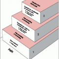
Cube:
1/8 of the activity in each face
2/8 of the activity in the core
Spacing
Constant uniform spacing
Crossing needles
Planar implant: Target area effectively treated is reduced in length by 10% per uncrossed end
Volume implant: Target volume effectively treated is reduced by 7.5% per uncrossed end
Elongation corrections
Long:short dimension:
1.5:1.0
2:1
2.5:1.0
3:1
4:1
Correction factors for mgRaEq-h
Planar:
1.025
1.05
1.07
1.09
1.12
Volume:
1.03
1.06
1.10
1.15
1.23
Source: From Williamson JF. Physics of brachytherapy. In: Perez CA, Brady LW, eds. Principles and practice of radiation oncology, 3rd ed. Philadelphia, PA: Lippincott-Raven, 1998:405-468, with permission.
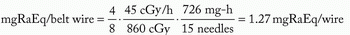
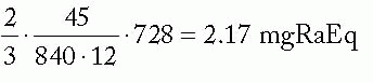
Figure 6-1 illustrates a classic Manchester implant with crossed ends, using iridium-192 (192Ir) line sources and 1-cm spacing to treat a cylindrical target volume 5 cm in diameter and 5 cm high. The required source strength is calculated as follows:
Target volume height = active needle length = 5 cm

Assume: minimum peripheral dose rate = 45 cGy per hour and belt:core:end:end = 4:2:1:1

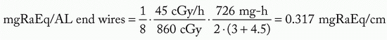
mgRaEq of each 3 cm wire = 3.0 ·3.317 = 0.95 mgRaEq
mgRaEq of each 4.5 cm wire = 4.5 · 0.317 = 1.42 mgRaEq
TABLE 6-3 Manchester Implant Tables
Volume Implants
Planar Implants
Volume (cm3)
mgRaEq-ha 1,000 P-PR
Minimum Dose/IRAKb cGy/(µGy·m2)
Area (cm2)
mgRaEq-ha 1,000 P-PR
Minimum Dose/IRAKb cGy/(µGy·m2)
1
34
3.49
0
30
4.48
2
54
2.20
2
97
1.38
3
70
1.68
4
141
0.953
4
85
1.38
6
177
0.759
5
99
1.194
8
206
0.652
10
158
0.752
10
235
0.572
15
207
0.574
12
261
0.515
20
251
0.474
14
288
0.466
25
291
0.408
16
315
0.426
30
329
0.361
18
342
0.393
40
398
0.298
20
368
0.365
50
462
0.257
24
417
0.322
60
522
0.228
28
466
0.288
70
579
0.206
32
513
0.262
80
633
0.188
36
558
0.241
90
684
0.174
40
603
0.223
100
734
0.162
44
644
0.209
110
782
0.152
48
685
0.196
120
829
0.143
52
725
0.185
140
919
0.129
56
762
0.176
160
1,005
0.118
60
800
0.168
180
1,087
0.110
64
837
0.160
200
1,166
0.102
68
873
0.154
220
1,242
0.0958
72
908
0.148
240
1,316
0.0904
76
945
0.142
260
1,389
0.0857
80
981
0.137
280
1,459
0.0815
84
1,016
0.132
300
1,528
0.0779
88
1,052
0.128
320
1,595
0.0746
92
1,087
0.124
340
1,661
0.0716
96
1,122
0.120
360
1,725
0.0690
100
1,155
0.116
380
1,788
0.0665
120
1,307
0.103
400
1,851
0.0643
140
1,463
0.0918
—
—
—
160
1,608
0.0835
—
—
—
180
1,746
0.0769
—
—
—
200
1,880
0.0715
—
—
—
220
2,008
0.0669
—
—
—
240
2,132
0.0630
—
—
—
260
2,256
0.0595
—
—
—
280
2,372
0.0566
—
—
—
300
2,495
0.0538
1,000 P-PR, 1,000 Manchester system roentgens; IRAK, integrated reference air-kerma.
a Original Manchester values from Paterson R, Parker HM. A dosage system for interstitial radium therapy. Br J Radiol 1938;11:313-339, with permission.
b Modified from original values for 192Ir, assuming 8.6 Gy minimum peripheral dose per 1,000 P-PR and 7.227 µGy·m2—mgRaEq-h.
From Williamson JF. Physics of brachytherapy. In: Perez CA, Brady LW, eds. Principles and practice of radiation oncology, 3rd ed. Philadelphia, PA: Lippincott-Raven, 1998:405-468, with permission.
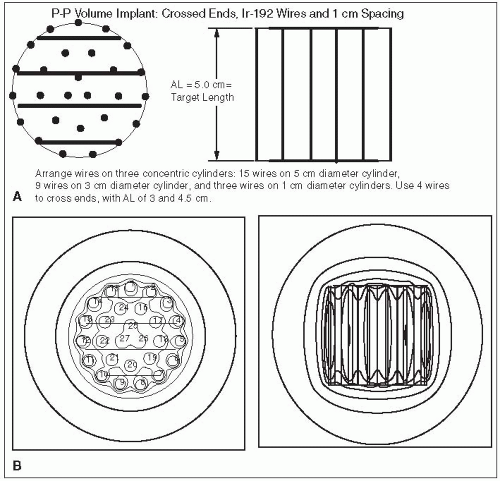
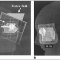
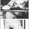
FIGURE 6-1 A: A 5-cm high by 5-cm diameter cylindrical target volume implanted with 35 differentially loaded wires spaced at 1-cm intervals. B: Resultant central transverse and coronal isodose curves plotted as percentages of the computer-calculated mean control dose (MCD) value of 56.3 cGy per hour (100%): 110% (62 cGy per hour), 100% (56 cGy per hour), 90% (51 cGy per hour), 80% (45 cGy per hour), 60% (34 cGy per hour), 40% (23 cGy per hour), and 11% (12 cGy per hour). Note that 80% of MCD, 45 cGy per hour, agrees exactly with the minimum peripheral dose rate of 45 cGy per hour predicted by the P-P tables. (From Williamson JF. Physics of brachytherapy. In: Perez CA, Brady LW, eds. Principles and practice of radiation oncology, 3rd ed. Philadelphia, PA: Lippincott-Raven, 1998:405-468, with permission.)
Figure 6-2 demonstrates that by increasing the interneedle spacing to 1.3 cm, the need for differential loading can be eliminated.
Because ends are uncrossed, required active length = target length/0.85 = 5.9 cm
Effective volume = π · (2.5)2 · 5.9 · 0.85 = 98.5 cm3, where
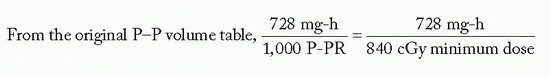
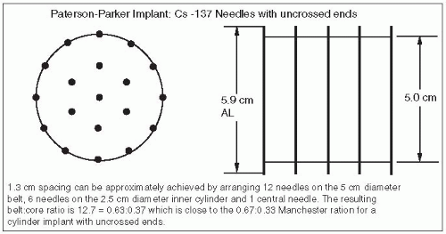
FIGURE 6-2 A 5 × 5-cm cylindrical volume implanted by uniform strength 137Cs needles spaced at 1.3-cm intervals. (From Williamson JF. Physics of brachytherapy. In: Perez CA, Brady LW, eds. Principles and practice of radiation oncology, 3rd ed. Philadelphia, PA: Lippincott-Raven, 1998:405-468, with permission.)
Assuming a minimum peripheral dose rate of 45 cGy/h and belt:core = 4:2,
mgRaEq/core needle =
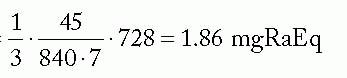
mgRaEq/belt needle =
Assuming uniform strength needles: mgRaEq/needle =
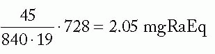
Figure 6-3 illustrates application of the Manchester system to the same 5 × 5 cm cylindrical target volume, using 192Ir ribbons with seed-to-seed spacing of 1 cm and an intercatheter spacing of 1.3 cm. Note that the distribution rules are satisfied almost exactly by using uniform seed strengths.
Assuming uncrossed ends, active length = target length/0.85 = 5.9 cm ⇒ 6 seeds/ribbon
Equivalently, the first and last seeds can be treated as “end” seeds, bisecting the target boundaries.
Either way, treated volume = π · (2.5)2 · 5.0 = 98.2 cm3

By choice of spacing, distribution rules are met by using seeds of equal strength.
To give 45 cGy/h, mgRaEq/seed
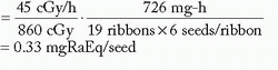
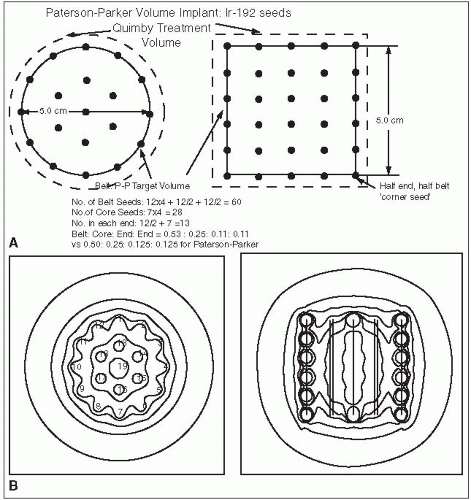
FIGURE 6-3 A: A 5 × 5-cm cylindrical target volume implanted with uniform-strength 192Ir ribbons spaced at 1.3-cm intervals. B: Resultant central transverse and coronal isodose curves normalized to the mean control dose (MCD) value of 58.9 cGy per hour (100%): 115% (68 cGy per hour), 100% (59 cGy per hour), 90% (53 cGy per hour), 80% (47 cGy per hour), 60% (35 cGy per hour), 40% (24 cGy per hour), and 20% (12 cGy per hour). Note that 80% of MCD, 47 cGy per hour, agrees closely with the minimum peripheral dose rate of 45 cGy per hour predicted by the P-P tables. (From Williamson JF. Physics of brachytherapy. In: Perez CA, Brady LW, eds. Principles and practice of radiation oncology, 3rd ed. Philadelphia, PA: Lippincott-Raven, 1998:405-468, with permission.)
Figure 6-4 illustrates application of the P-P system to a modern planar implant.
As both ends are uncrossed, active length is greater than target length/0.92 = 5/0.81 = 6.2 cm
The shortest ribbon of active length > 6.2 cm contains seven seeds (AL = 7 cm)Related posts:

Stay updated, free articles. Join our Telegram channel

Full access? Get Clinical Tree