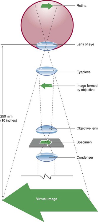
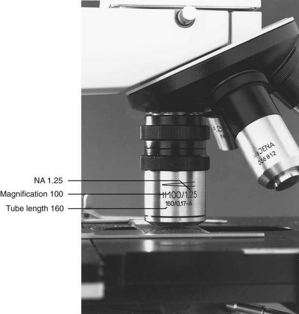
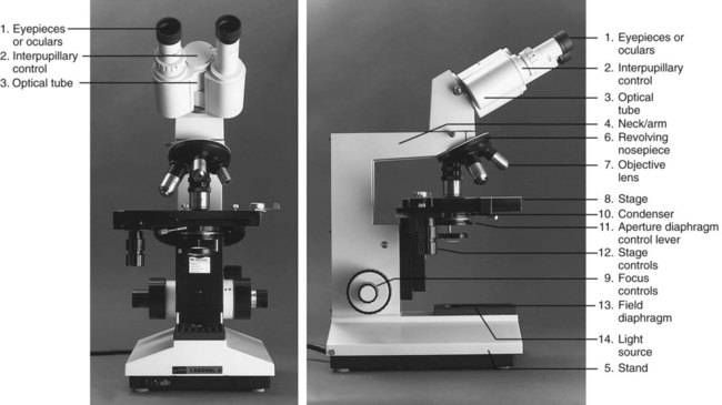
After completion of this chapter, the reader will be able to: 1. Given either a diagram or an actual brightfield light microscope, identify the component parts. 2. Explain the function of each component of a brightfield light microscope. 3. Define achromatic, planachromatic, parfocal, and parcentric as applied to lenses and microscopes; explain the advantages and disadvantages of each; and recognize examples of each from written descriptions of microscope use and effects. 4. Explain the purpose of adjusting microscope light using a procedure such as Koehler illumination. 5. List in proper order the steps for adjusting a brightfield light microscope using Koehler illumination. 6. Using the procedure provided in the text and a brightfield light microscope with appropriate components, properly adjust a brightfield light microscope by the use of Koehler illumination. 7. Describe the proper steps for viewing a stained blood film with a brightfield light microscope, including use of oil immersion lenses, and recognize deviations from these procedures. 8. Using the procedure described in the text and a brightfield light microscope with appropriate lenses, focus a stained blood film with dry and oil immersion objectives. 9. Describe the proper care and cleaning of microscopes and recognize deviations from these procedures. 10. Using the procedures described in the text and a microscope, properly clean the microscope after routine use. 11. Given the magnification of lenses in a compound microscope, calculate the total magnification. 12. Given a problem with focusing a blood film using a brightfield light microscope, suggest possible causes and their correction. 13. For each of the following, describe which components of the microscope differ from those of a standard light microscope, what the differences accomplish, and what are the uses and benefits of each type in the clinical laboratory: Microscopes available today reflect improvement in every aspect from the first microscope of Anton van Leeuwenhoek (1632-1723).1 Advanced technology as applied to microscopy has resulted in computer-designed lens systems, sturdier stands, perfected condensers, and built-in illumination systems. Microscopes can be fitted with multiple viewing heads for teaching or conferences, or they can be attached to a computer to allow an object to be projected onto a monitor or a large screen. Regular care and proper cleaning ensure continued service from this powerful diagnostic instrument. The references listed at the end of this chapter address the physical laws of light and illumination as applied to microscopy. Component parts and the function of each part of the microscope are summarized as follows (Figure 4-2): 1. The oculars, or eyepieces, usually are equipped with 10× lenses (degree of magnification is 10×). The lenses magnify the intermediate image formed by the objective lens in the optical tube; they also limit the area of visibility. Microscopes may have either one or two adjustable oculars. All oculars should be used correctly for optimal focus (see section on operating procedure). Oculars should not be interchanged with the oculars of other models of microscopes. The oculars in a pair are optically matched. 2. The interpupillary control is used to adjust the lateral separation of the oculars for each individual. When it is properly adjusted, the user should be able to focus both eyes comfortably on the specimen and visualize one clear image. 3. The optical tube connects the oculars with the objective lens. The intermediate image is formed in this component. The standard length is 160 mm, which, functionally, is the distance from the real image plane (oculars) to the objective lenses. 4. The neck, or arm, provides a structural site of attachment for the revolving nosepiece. 5. The stand is the main vertical support of the microscope. The stage assembly, together with the condenser and base, is supported by the stand. 6. The revolving nosepiece holds the objectives and allows for easy rotation from one objective lens to another. The working distance between the objectives and the slide varies with the make and model of the microscope. 7. There are usually three or four objective lenses (Figure 4-3), each with a specific power of magnification. Engraved on the barrel of each objective lens is the power of magnification and the numerical aperture (NA). The NA is related to the angle of light collected by the objective; in essence, it indicates the light-gathering ability of the objective lens. Functionally, the larger the NA, the greater the resolution or the ability to distinguish between fine details of two closely situated objects. Microscopes employed in the clinical laboratory are used with achromatic or planachromatic objective lenses, whose function is to correct for chromatic and spheric aberrations. Chromatic aberrations are caused by the spheric surface of the lens, which acts as a prism. As the various wavelengths pass through the lens, each focuses at a different point, which gives rise to concentric rings of color near the periphery of the lens. Spheric aberrations result as light waves travel through the varying thicknesses of the lens, blurring the image. The achromatic objective lens brings light of two colors into focus, partially correcting for the aberrations. When achromatic objective lenses are used, the center of the field is in focus, whereas the periphery is not. A planachromatic lens, which is more expensive, also corrects for curvature of the field, which results in a flat field with uniform focus.2 Planachromatic lenses sometimes are referred to as flat field lenses. For critical microscopy, a planapochromatic lens, which brings light of three colors into focus and almost completely corrects for chromatic aberration, may be used. This type of objective lens is fairly expensive and is rarely needed for routine laboratory use. 8. The stage supports the prepared microscope slide to be reviewed. A spring assembly secures the slide to the stage. 9. The focus controls (or adjustments) can be incorporated into one knob or can be two separate controls. When a single knob is used, moving it in one direction engages the coarse control, whereas moving it in the opposite direction engages the fine control. One gradation interval of turning is equivalent to 2 µm. Many microscopes are equipped with two separate adjustments: one coarse and one fine. The order of usage is the same: engage the coarse adjustment first and then fine-tune with the fine adjustment. 10. The condenser, consisting of several lenses in a unit, may be permanently mounted or vertically adjustable with a rack-and-pinion mechanism. It gathers, organizes, and directs the light through the specimen. Attached to and at the bottom of the condenser is the aperture diaphragm, an adjustable iris containing numerous leaves that control the angle and amount of the light sent through the specimen. The angle, also expressed as an NA, regulates the balance between contrast (ability to enhance parts within a cell) and resolution (ability to differentiate fine details of two closely situated objects). The best resolution is achieved when the iris is used fully open, but there is some sacrifice of image contrast. In practice, this iris is closed only enough to create a slight increase in image contrast. Closing it beyond this point leads to a loss of resolution. Some microscopes are equipped with a swing-out lens immediately above or below the main condenser lens. This lens is used to permit a wider field of illumination when the NA of the objective lens is less than 0.25 (e.g., the 4×/0.12 objective lens).3 If the swing-out lens is above the main condenser, it should be out for use with the 4× objective lens and in for lenses with magnification of 10× and higher. If it is below the condenser, it should be in for use with the 4× objective lens and out for lenses of magnification of 10× and higher. The 4× objective is not used routinely for examination of peripheral blood films. The stage and condenser (Figure 4-4
Care and Use of the Microscope
Component Parts and Function of Each Part
Related posts:
![]()
Stay updated, free articles. Join our Telegram channel

Full access? Get Clinical Tree


Care and Use of the Microscope