Beam Dosimetry, Physics, and Clinical Applications
Beam Dosimetry, Physics, and Clinical Applications
CLINICAL PHOTON BEAM DOSIMETRY
Single-Field Isodose Distributions
The central axis percentage depth dose (PDD) expresses the penetrability of a radiation beam.
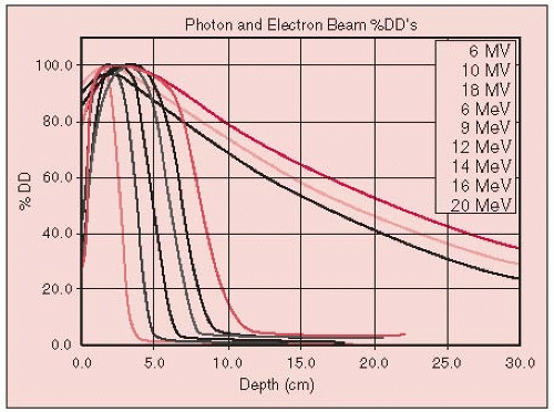
Beam characteristics for x-ray and gamma-ray beams typically used in radiation therapy, the depth at which the dose is maximum (100%), and the PDD value at 10-cm depth are summarized in Table 2-1 and Figure 2-1.
For a 10 × 10-cm field, 18- and 6-MV x-ray beams and cobalt-60 (60Co) beams (1.25 MV average x-ray energy) lose approximately 2.0%, 3.5%, and 4.5% per cm, respectively, beyond the depth of maximum dose (dmax).
Cobalt units exhibit a large penumbra, and their isodose distributions are rounded toward the source as a result of the relatively large source size (typically 1 to 2 cm in diameter). Linear accelerator (linac) isodose distributions have much smaller penumbras and relatively flat isod ose curves at depth.
Buildup Region
The buildup region is very energy dependent (Fig. 2-1).
If the x-ray beam is incident normal (at 0 degrees) to the surface, maximum skin sparing is achieved.
Skin dose increases and dmax moves toward the surface as the angle of incidence increases. This is because more secondary electrons are ejected along the oblique path of the beam, a phenomenon called tangential effect (7, 8, 9, 22).
Tissue Heterogeneities
Perturbation of photon transport is more noticeable for lower-energy beams.
For a modest lung thickness of 10 cm, there will be an approximately 15% increase in the dose to the lung for a60Co or 6-MV x-ray beam (24), but only an approximately 5% increase for an 18-MV x-ray beam (17) (Fig. 2-2).
Measurements performed with a parallel-plate ionization chamber for cobalt showed significant losses of ionization on the central axis following air cavities of varying dimensions. Due to lack of forward-scattered electrons, the losses were approximately 12% for a typical laryngeal air cavity, but were recovered within 5 mm in the new buildup region (4).
Klein et al. (12), using a parallel-plate chamber in both the distal and proximal regions, observed a 10% loss at the interfaces for an air cavity of 2 × 2 × 2 cm for 4 × 4-cm parallel-opposed fields for 4-MV and 15-MV photons. They also observed losses at the lateral interfaces perpendicular to the beam on the order of 5% for a 4-MV beam.
TABLE 2-1 Beam Characteristics for Photon Beam Energies of Interest in Radiation Therapy
200 kV(p) (kilovolt [peak]); 2.0 mm Cu half-value layer (HVL); source to skin distance (SSD) = 50 cm
Depth of maximum dose = surface
Rapid falloff with depth due to (a) low energy and (b) short SSD
Sharp beam edge due to small focal spot
Significant dose outside beam boundaries due to Compton scattered radiation at low energies
60Co, SSD = 80 cm
Depth of maximum dose = 0.5 cm
Increased penetration (10-cm PDD = 55%)
Beam edge not as well-defined—penumbra due to source size
Dose outside beam low because most scattering is in forward direction
Isodose curvature increases as the field size increases
4-MV x-ray; SSD = 80 cm
Depth of maximum dose = 1.0-1.2 cm
Penetration slightly greater than cobalt (10 cm PDD = 61%)
Penumbra smaller
“Horns” (beam intensity off axis) due to flattening filter design can be significant (14%)
6-MV x-ray; SSD = 100 cm
Depth of maximum dose = 1.5 cm
Slightly more penetration than60Co and 4-MV (10 cm PDD = 67%)
Small penumbra
“Horns” (beam intensity off axis) due to flattening filter design reduced (9%)
18-MV x-ray; SSD = 100 cm
Depth of maximum dose = 3.0-3.5 cm
Much greater penetration (10 cm PDD = 80%)
Small penumbra
“Horns” (beam intensity off axis) due to flattening filter design reduced (5%)
Exit dose often higher than entrance dose
FIGURE 2-1 Central axis PDD for megavoltage x-rays (60Co to 18 MV—long tailed curves to right) and also electron beams (6 to 20 MeV). (From Halperin EC, Perez CA, Brady LW. Principles and practice of radiation oncology,5th ed. Philadelphia, PA: Lippincott Williams & Wilkins, 2008:160, with permission.)
FIGURE 2-2 Percentage increase in lung dose as a function of depth in the lung for selected energies. Field size is 10 × 10 cm. (From McDonald SC, Keller BE, Rubin P. Method for calculating dose when lung tissue lies in the treatment field. Med Phys 1976;3:210, with permission.)
Prostheses (Steel and Silicon)
Das et al. (2) measured forward dose perturbation factors following a 10.5-mm-thick stainless steel layer simulating a hip prosthesis geometry. They reported an enhancement of 19% for 24 MV photons, but only 3% for 6 MV photons. They also measured backscatter dose perturbation factors for various energies and many high-Z materials, including steel, and observed an enhancement of 30% for steel due to backscattered electrons, independent of the energy, field size, or lateral extent of the steel.
Klein and Kuske (13) reported on interface perturbations with silicon breast prostheses, which have a density similar to breast tissue but a different atomic number. They observed a 6% enhancement at the proximal interface and a 9% loss at the distal interface.
Wedge Filters
The term wedge angle refers to the angle through which an isodose curve is tilted at the central ray of a beam at a specified depth.
For cobalt units, the depth of the 50% isodose line is usually selected for specification of the wedge angle, whereas for higher-energy linacs, higher-percentile isodose curves, such as the 80% curve, or isodose curves at a specific depth (e.g., 10 cm) are used to define the wedge angle. Modern computer-controlled medical linacs have software features that allow the users to create a wedge-shaped dose distribution by moving one collimator jaw across the field with adjustment of the dose rate over the course of the daily single-field treatment (14) (i.e., dynamic wedge).
When a patient’s treatment is planned, wedged fields are commonly arranged such that the angle between the beams (the hinge angle, φ) is related to the wedge angle, θ, by the relationship: θ = 90 degrees — φ/2.
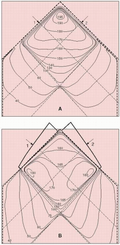
As shown in Figure 2-3, 45-degree wedges orthogonal to one another yield a uniform dose distribution.
Parallel-Opposed Fields
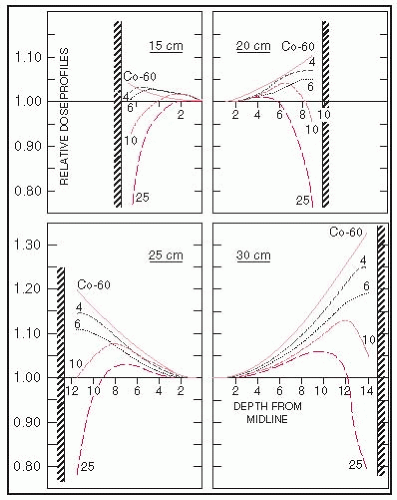
Figure 2-4 shows the normalized relative-axis dose profiles from parallel-opposed photon beams for a 10 × 10-cm field at source to skin distance (SSD) of 100 cm and for patient diameters of 15 to 30 cm in 5-cm increments.
FIGURE 2-3 Isodose distribution for two angle beams. A: Without wedges. B: With wedges. (4 MV; field size, 10 × 10 cm; SSD, 100 cm; wedge angle, 45 degrees.) (From Khan FM. The physics of radiation therapy, 3rd ed. Baltimore, MD: Williams & Wilkins, 1994, with permission.)
The maximum patient diameter easily treated with parallel-opposed beams for a midplane tumor with low-energy megavoltage beams is approximately 18 cm.
For thicker patients, higher x-ray energies produce improved dose profiles and reduce hot spots in the entry and exit regions.
FIGURE 2-4 Relative central-axis dose profiles as a function of x-ray energy (60Co or 4, 6, 10, and 18 MV) and patient thickness (15, 20, 25, and 30 cm). The parallel-opposed beams are equally weighted, and the profiles are normalized to unity at midline. Because of symmetry, only half of each profile is shown. (From Purdy JA, Klein EE. Photon external beam dosimetry and treatment planning. In: Halperin, EC, Perez CA, Brady LW, eds. Principles and practice of radiation oncology, 5th ed. Philadelphia, PA: Lippincott Williams & Wilkins, 2008:166-189, with permission.)
FIELD SHAPING
Cerrobend, probably the most commonly used metal alloy, consists of 13.3% tin, 50.0% bismuth, 26.7% lead, and 10.0% cadmium. The physical density at 20°C is 9.4 g per cm3, compared with 11.3 g per cm3 for lead. The total time required for the block to solidify is typically approximately 45 minutes.
Doses to critical organs may be limited by using either a full shielding block—usually 5 half-value layer (HVL) (3.125% transmission) or 6 HVL (1.562% transmission)—or a partial transmission block, such as a single HVL (50% transmission) of shielding material.
The true percentage dose level is generally greater than the percentage stated because of scattered radiation beneath the blocks from adjacent unshielded portions of the field and increases with depth as more radiation scatters into the shielded volume beneath the shield.
At present, multileaf collimation is increasingly used in lieu of Cerrobend blocking on compatible linacs.
COMPENSATING FILTERS
A compensating-filter system includes methods for measuring the missing-tissue deficit, demagnifying patient topography, constructing the compensating filter, aligning and holding the filter in the beam, and performing quality control.
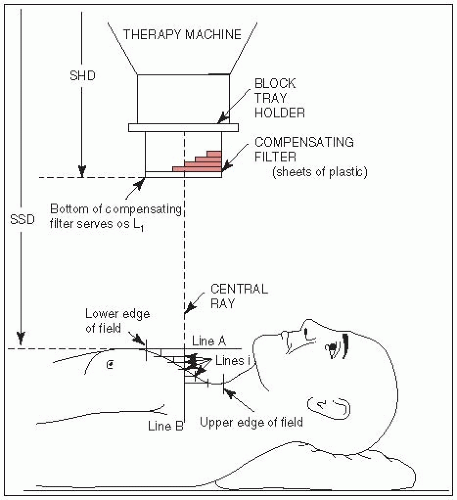
FIGURE 2-5 One-dimensional chest compensating-filter system using sheets of plastic. (From Purdy JA, Klein EE. External photon beam dosimetry and treatment planning. In: Perez CA, Brady LW, eds. Principles and practice of radiation oncology, 3rd ed. Philadelphia, PA: Lippincott-Raven, 1998:281-320, with permission.)
Purdy et al. (19) developed a one-dimensional compensating system designed for individual patient chest curvatures using Lucite plates. The SSD is set to the highest point of the anatomic area (chest) to be irradiated (Fig. 2-5). A sagittal contour of the chest is obtained, and the number of layers of Lucite, each with thickness equivalent to 1 cm of tissue, is obtained as well.
A practical two-dimensional compensator system is still widely used (3). A rod-box device (a formulator) is used to measure the tissue deficit in a 1-cm grid over the treatment surface. Blocks of aluminum or brass of appropriate thickness are then mounted on a tray above the patient to attenuate the beam by the desired amount. Beam divergence also may be incorporated into this system.
BOLUS
Tissue-equivalent material placed directly on the patient’s skin surface to reduce the skin sparing of megavoltage photon beams is referred to as bolus.
A tissue-equivalent bolus should have electron density, physical density, and atomic number similar to that of tissue or water, and it should be pliable so that it conforms to the skin surface contour.
Inexpensive, nearly tissue-equivalent materials used as a bolus in radiation therapy include slabs of paraffin wax, rice bags filled with soda, and gauze coated with petrolatum.
SEPARATION OF ADJACENT X-RAY FIELDS
Field Junctions
A commonly used method matches adjacent radiation fields at depth.
The necessary separation between adjacent field edges needed to produce junction doses similar to central-axis doses follows from the similar triangles formed by the half-field length and SSD in each field. The field edge is defined by the dose at the edge that is 50% of the dose at dmax.
Consider two contiguous fields of lengths L1 and L2; the separation, S, of these two fields at the skin surface follows from these expressions:
Only gold members can continue reading. Log In or Register to continue