Applied Anatomy and Target Volume Definition
During most of the 20th century, radiation therapy treatment plans were based on external beam fields whose borders were drawn directly on x-ray films. For most gynecologic treatments, the borders of pelvic fields were drawn in relation to skeletal landmarks and fixed reference points on AP-PA and lateral x-ray films. Treatments designed in this way cured many gynecologic cancers, and the outcomes of treated patients confirmed that these conventional fields encompassed the central and regional targets that were most likely to harbor microscopic disease.
As demonstrated below, pelvic fields designed using these traditional methods are remarkably similar to fields that are shaped to conform to precise CT-guided target volumes. However, the traditional two-dimensional method of treatment planning can lead to underdosage of unappreciated regions of gross disease. Furthermore, early experiences with conformal treatment quickly revealed the dangers of implementing new technology without fully understanding the anatomy of the target region. For example, in the 1980s, a move to use electrons to treat the groins of patients with vulvar cancer rapidly revealed that the traditional prescription depth of 3 cm, used for many years to prescribe photon treatment of the groin, was not a good surrogate for the inguinofemoral target volume when the beam actually conformed to that depth. Unfortunately, the evidence came in the form of fatal groin recurrences.1,2
The 21st century has witnessed a sea change in gynecologic radiation therapy treatment planning. Intensity modulated radiation therapy (IMRT) is increasingly being used to generate plans that conform closely to physician-designated CT-based target volumes. Although IMRT can reduce the side effects of radiation therapy, its effectiveness is highly dependent on the accuracy of the designated target volumes and, therefore, on the radiation oncologist’s understanding of regional anatomy and patterns of disease dissemination. Image-based planning also requires an appreciation for the value and limitations of diagnostic imaging modalities. Even when relatively simple three-dimensional plans are used for pelvic treatment, serious errors and unnecessary recurrences can occur if the field borders are based on inappropriate target volumes. For this reason, it is helpful to understand the relationship between target volumes and the traditional, long-tested fields that were based on bony landmarks.
In this chapter, relevant structures will be depicted in several ways to demonstrate not only their appearance on CT or MRI but also their relationships to bony, surface, and vascular anatomy. The influence of internal organ motion on target volume designation will also be discussed. The developmental origins of müllerian and lymphatic structures will be described to help explain adult anatomy and characteristic patterns of regional metastasis.
TARGET VOLUME DEFINITION
Accurate target volume definition requires a thorough understanding of:
Locoregional anatomy, including normal variations,
Gynecologic diagnostic imaging modalities,
Operative findings and associated histologic findings,
The natural history and patterns of spread of various disease processes,
The nature of internal organ motion,
The potential for tumor response and other anatomic changes during treatment, and
Uncertainties in daily setup accuracy.
This information is used to determine an overall treatment strategy and to define various components of the final radiation therapy target volumes. In clinical practice, these components are not always defined consistently. This can lead to miscommunications in target volume definition. For this book and in our practice, components of the target volume are defined as follows:
Clinical target volume (CTV): A region with sufficient risk for containing disease to warrant targeted treatment. The CTV includes solely those tissues, as seen on the treatment planning CT scan, that are considered at risk for primary involvement, lymphatic spread, or direct extension to adjacent tissues. In most cases, for definitive treatment of gynecologic carcinomas, the CTV receives a minimum dose of 40 to 45 Gy of fractionated radiation therapy.
High-risk CTV: A region of potential microscopic disease for which doses of more than 45 Gy may be required to achieve high rates of disease control. Examples include positive or close resection margins, equivocal lymph nodes, and sites of extracapsular extension.
Internal target volume (ITV): An expanded target volume designated to account for intertreatment and intratreatment motion of a CTV or GTV. This often involves the integration of information from two or more imaging studies.
Gross tumor volume (GTV): An area of gross disease identified by imaging, physical examination, or intraoperative findings. Several GTVs may be designated to define regions requiring different radiation doses.
Planning target volume (PTV): A CTV, ITV, or GTV plus a margin added to account for variability in patient setup and table alignment. In our practice, the physician usually designates the targets described above and specifies a margin to be added by the dosimetrist prior to inverse planning (Chapter 6).
Nested interior GTV: This term will be used to describe internal target volumes that are sometimes specified to treat the interiors of very large tumor masses at a higher dose per fraction than the GTV-PTV; typically, this is a PTV that excludes all vulnerable critical structures (and therefore excludes a portion of the GTV-PTV). The goal is to accelerate the tumor response to facilitate boost planning although the ultimate impact on local tumor control is not known.
In general, bone, muscle, intraperitoneal contents, and other tissues not suspected of harboring disease are not included in the designated CTVs or GTVs. However, an ITV is designated where appropriate to account for internal organ motion, and a PTV margin is always added to GTVs, CTVs, and ITVs to account for other uncertainties, particularly setup inaccuracies.
Throughout this chapter, suggested target volumes should be viewed as examples that may vary with the clinical situation.
REGIONAL LYMPH NODES
Regional lymph nodes are included in the target of most definitive gynecologic radiation treatments. Radiation therapy is an effective tool in the treatment of many gynecologic malignancies in large part because regional spread frequently occurs well before the development of hematogenous metastasis, increasing the likelihood that effective regional treatment will be curative.
Overview of Vascular and Lymphatic Development
The lymphatic system develops in parallel with the embryonic venous (not the arterial) system in a fashion that explains many anatomic features of the adult (Fig. 5.1). At the end of the 5th week of fetal development, endothelium-lined lymphatic sacs appear in the jugular, retroperitoneal, and iliac regions; from these sacs, lymphatic vessels emerge and grow along the course of embryonic veins. Subsequently, clusters of lymph nodes develop in the regions of the lymph sacs and eventually along the course of major lymph vessels. Most of the lymphatic vessels supplying the central pelvic organs originate from paired posterior lymph sacs located at the junction of the primitive supracardinal and iliac veins. This region, at and just below the junction of the common iliac, internal iliac, and external iliac veins, is the most frequent site of pelvic node metastases from cervical cancer and other central pelvic malignancies (Fig. 5.2).3
Fetal venous development is also the best context in which to understand the asymmetric distribution of the paraaortic nodes and patterns of paraaortic lymphatic spread. The inferior vena cava is a compound structure formed by the fusion of right supracardinal vein and other portions of the early venous system (Fig. 5.1). Although the left supracardinal vein eventually disappears, it is present during the most active period of lymphatic development, and its associated lymphatic vessels and nodes persist, forming the left paraaortic lymphatic chain. Whereas the paracaval nodes are virtually always in direct contact with the vena cava, the left infrarenal paraaortic nodes can be found anywhere within the 1- to 2-cm space between the aorta and the left psoas muscle, reflecting their association with the supracardinal vein that once occupied this space.4 The drainage of the left ovarian vein into the renal vein and the distribution of aortic nodes at the renal level are also evidence of this asymmetric development. These features have important implications for contouring of nodal CTVs in this region.
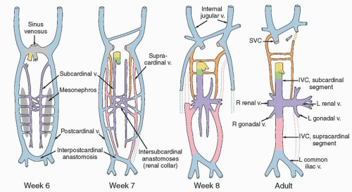 FIGURE 5.1 Venous development. Comparison of embryonic venous structures during weeks 6, 7, and 8 and venous structures in the adult. The abdominopelvic veins develop from longitudinal pairs and anastomoses of subcardinal (purple), postcardinal (blue), and supracardinal (pink) veins. Various segments expand, coalesce, diminish, and even disappear as the fetus matures. The lymphatic system begins to develop in the 5th week, when lymphatic vessels emerge from primitive fetal sacs and extend to follow the paths of the fetal veins. Lymphatics to the left of the aorta follow the course of the left supracardinal vein, which subsequently disappears. Note that the origin of the left common iliac vein from the interpostcardinal anastomosis differs from that of the right common iliac vein. This explains the greater length and near horizontal path of the left common iliac vein and possibly the asymmetric distribution of common iliac nodes described in Figure 5.2. (Adapted from Standrig S. Gray’s Anatomy: The Anatomical Basis of Clinical Practice. 40th ed. Philadelphia, PA: Churchill Livingstone; 2008.) (IVC, inferior vena cava; L, left; R, right; SVC, superior vena cava; v., vein.) |
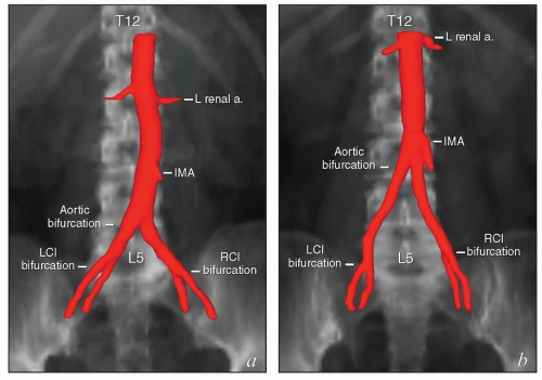
Although it is common to describe the locations of lymph nodes in terms of their relationships to arterial landmarks, this practice can lead to erroneous assumptions. During development, branches of the dorsal aorta migrate considerable distances as the corresponding organs develop. As a result, the final locations of the origins of the mesenteric and renal arteries and the lengths of intervening aortic segments vary significantly between patients (Fig. 5.3). The vertebral level of the aortic bifurcation is also highly variable, and the bifurcations of the common iliac arteries, though usually within 1 to 1.5 cm of the L5/S1 interspace, can also be found outside that range. For these reasons, the proximal vertebral level of radiation field borders does not always provide an accurate estimate of the adequacy of nodal coverage.
It is important to note that the common iliac vessels are not located in the true pelvis. Although clinicians frequently refer to sites of possible nodal involvement as “pelvic” or “aortic,” the common iliac nodes do not fit into either of these designations. Studies of patients treated with pelvic radiation for cervical cancer demonstrate that the common iliac nodes immediately above the treatment field are common sites of nodal recurrence.5 These “iliac” recurrences are frequently misidentified as pelvic and may be incorrectly assumed to be located within the previous pelvic radiation treatment field. To avoid confusion, nodal recurrences should be specified in terms of their precise anatomic location (external iliac, internal iliac, common iliac, or paraaortic) as well as their vertebral level and relationship to radiation treatment fields.
Definition of Nodal Clinical Target Volumes
Optimal nodal target volume definition requires an understanding of the patterns of lymphatic drainage and of the tissue compartments that house the pelvic, paraaortic, and inguinal lymph nodes.
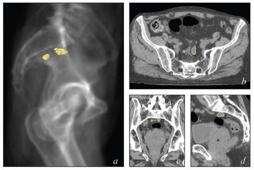
Nodal target volumes cannot be defined accurately by simply surrounding the major vessels with a fixed margin. The distribution of lymph nodes around the major vessels is not symmetric, and although many relevant lymph nodes do lie immediately adjacent to large vessels, others do not. The hypogastric vessels, sacral vessels, and relevant branches of the femoral vessels are difficult to identify on axial CT slices but are associated with important sites of regional metastasis from gynecologic cancers.
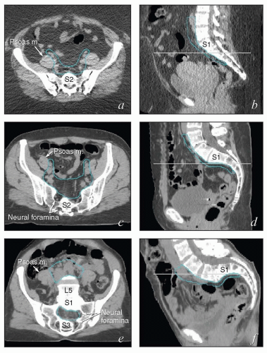
Also, although contouring atlases can be helpful to clinicians who are developing their skills, the appearance of the nodal target volumes on an axial plane can vary dramatically according to the configuration of the pelvis (Fig. 5.4). For this reason, axial contouring should be performed while the clinician references coronal and sagittal reconstructions to be certain that the target volumes are consistent and make sense in three dimensions.
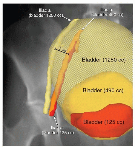
Finally, although the positions of the pelvic and abdominal lymph nodes tend to be fairly constant, lymph nodes can be displaced by large soft tissue masses. In addition, hyperexpansion of the bladder can compress the psoas muscles and displace iliac vessels and lymph nodes (Fig. 5.5); for this and other reasons (Chapter 4), patients should be discouraged from having an uncomfortably full bladder during treatment. Treatment
planning should not be based on a planning CT scan in which the bladder volume is more than about 500 to 600 mL (or extending above the base of the sacroiliac joints) without confirmation that vessel positions are similar when the bladder is less full. Large seromas can also displace adjacent vessels, and the displacement may change with seroma volume. Absent these special circumstances, intratreatment movement of the pelvic nodes tends to be <2 to 3 mm. Because day-to-day variations in lymph node positions are usually small, generalized, and difficult to quantitate for individual patients, this is one type of internal organ motion that may reasonably be accounted for with an adequate (6 to 7 mm) PTV margin (Chapter 6).
planning should not be based on a planning CT scan in which the bladder volume is more than about 500 to 600 mL (or extending above the base of the sacroiliac joints) without confirmation that vessel positions are similar when the bladder is less full. Large seromas can also displace adjacent vessels, and the displacement may change with seroma volume. Absent these special circumstances, intratreatment movement of the pelvic nodes tends to be <2 to 3 mm. Because day-to-day variations in lymph node positions are usually small, generalized, and difficult to quantitate for individual patients, this is one type of internal organ motion that may reasonably be accounted for with an adequate (6 to 7 mm) PTV margin (Chapter 6).
Pelvic and Common Iliac Lymph Nodes
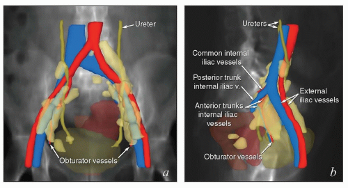
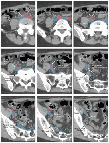
The lymphatic drainage of the vulva, vagina, uterus, and ovaries is discussed in detail with the anatomy of these structures later in this chapter. The pelvic nodes most commonly affected by metastasis from the reproductive organs are those that lie between the internal and external iliac vessels near the bifurcations of the common iliac veins and those associated with the anterior branches of the internal iliac vessels (Fig. 5.2)3; however, other nodes, including sacral, gluteal, and pararectal nodes, can be involved under some circumstances (Figs. 5.2 and 5.6; Table 5.1). A detailed discussion of the CTV for postoperative regional treatment of uterine cancers is included in the annotations accompanying Figure 5.7. The three-dimensional appearance of this CTV and its relationship to typical AP and lateral pelvic fields is shown in Figure 5.8. However, the axial appearance of the pelvic node CTV can vary considerably according to the position of the pelvis (Fig. 5.4).
Paraaortic Lymph Nodes
The lymph nodes adjacent to the vena cava and aorta receive lymphatic drainage from the pelvis and also, as discussed below, can be sites of primary lymphatic drainage from the uterine fundus, tubes, and ovaries. A detailed discussion of paraaortic target volume definition is included in the annotations accompanying Figure 5.9. The three-dimensional relationships between lymph nodes and associated vascular structures and the appearance of typical AP and lateral fields designed to cover the paraaortic CTV are illustrated in Figure 5.10.
Inguinal Lymph Nodes
The inguinal lymph nodes receive lymphatic drainage from the vulva, distal vagina, mons pubis, and distal anterior abdominal wall (Table 5.1). Lymphatics of the external genitalia reach the groin via the superficial external pudendal and external epigastric lymphatic vessels. The more lateral (superficial circumflex) lymph nodes are rarely if ever the initial site of involvement but can be involved secondarily. A detailed discussion of inguinal target volume definition is included in the annotations accompanying Figure 5.11. The relationships between vascular structures, bony landmarks, and a three-dimensional view of a suggested CTV for comprehensive treatment of the relevant inguinal nodes are shown in Figure 5.12.
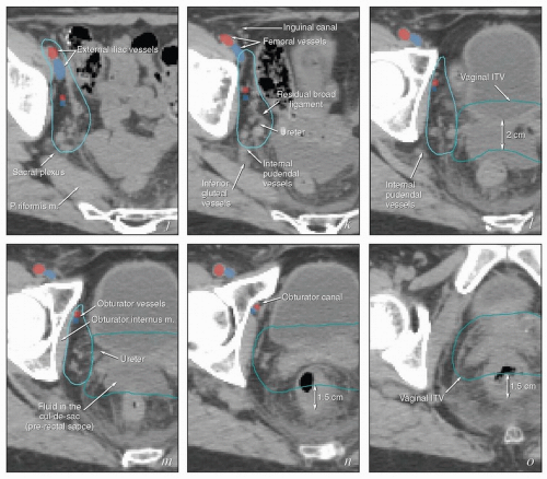 FIGURE 5.7 (Continued) The external iliac nodes typically lie posterior, medial, or occasionally anterior to the external iliac vessels but rarely if ever between the vessels and the psoas muscle. For this reason, the lateral border of the iliac CTV generally follows the medial border of the psoas muscle (a-j). Particular care should be taken not to confuse the medial portion of the psoas muscle (i) with the external iliac vessels, whose location can sometimes be obscure on non-contrastenhanced CT. Unless there are enlarged nodes, the CTV should be placed 3 to 4 mm from the external iliac vessels in the anterior and medial directions. Because the intra-iliac region (posterior to the external iliac vessels; c-m) is the most frequent site of pelvic node metastasis from gynecologic cancers, generous coverage of all the vessels in this space (typically at or near the interface with bowel and abutting adjacent muscle or bone) is necessary. Just above the level of the acetabulum, the external iliac vessels begin to deviate laterally in their descent toward the inguinal canal where they become the femoral vessels (k); unless the distal vagina is involved with cancer, the CTV does not need to include the vessels distal to this level. Presacral node CTV. Because the contours shown here are for a patient who has tumor in the cervix, the contours extend to cover the presacral nodes to mid-S3 (d-h, q). For uterine body cancers, the distal presacral region may be reduced slightly, but the region anterior to S1 and S2 should still be treated. Coverage of the presacral nodes is also discussed in the legends for Figures 5.4 and 5.6. Uterine ligaments. After simple hysterectomy, the residual broad ligament and associated parametrial tissues retract to a position medial to the obturator internus muscle and internal iliac vessels; for this reason, any soft tissue that remains between these structures and bladder or bowel should be included in the CTV (j-m). Although the nodal CTV is usually discontinued distally at the level of the obturator canal, the paravaginal tissues must still be included in the CTV. Vaginal ITV. Although the patient’s bladder volume on the day of this simulation was only 100 mL, a diagnostic scan when the patient’s bladder volume was 400 mL was used to estimate the influence of bladder volume on vaginal position. Teal lines (l-p) indicate a suggested vaginal ITV generated using the fused scans. The target included the vagina as well as paravaginal tissues at risk. Because the rectum was moderately full, the vaginal ITV was extended posteriorly to within 1.5 cm of the posterior rectal wall. At the apex of the vagina, the rectum reflects back toward the sacrum; the resulting prerectal space is typically filled with bowel or, as in this case, resolving postoperative fluid collections (k-m). A 2-cm posterior margin was used in this region. Scrutiny of reconstructed coronal views (p, q) provides an important check on the consistency and accuracy of axial contouring (see Figure 5.19). Reference to contrast-enhanced CT or MRI can be very helpful in identification of the vessels (discussed in Chapter 4). Note: To account for setup uncertainties, the CTV and ITV must be expanded (usually by 6 to 7 mm) to account for setup variability; the resulting PTV should be used to generate the final plan. |
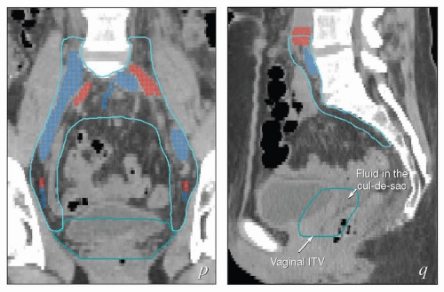 FIGURE 5.8 Relationship between regional target volumes and typical radiation therapy field arrangements for posthysterectomy pelvic treatment. (a, b) Three-dimensional reconstructions of the nodal CTV (cyan), vaginal ITV (teal), and selected vascular structures outlined in Figure 5.7 superimposed on a digitally reconstructed radiograph. Typical anterior and lateral fields that would be used for a four-field box arrangement have been added. Note how closely these fields conform to the designated target volumes, allowing margin for geometric penumbra and patient setup uncertainties. In (c) and (d), fields are shown without superimposed structures to more clearly demonstrate the relationship between suggested field borders and bony landmarks. Typical anterior fields (c) extend inferiorly to at least the mid-pubis or 4 cm beyond the vaginal apex; the lateral field border is usually 1.5 to 2 cm lateral to the pelvic brim. Each inferior corner block extends from a point at the intersection between the lateral field edge and the top of the acetabulum (1) passes along the outer margin of the obturator foramen and intersects with the inferior border of the field (2). Superior blocks extend proximally from the lateral edge of the field (3) to a point just outside the proximal SI joint (4), and then continue superiorly to intersect with the proximal border of the field. The posterior border of the lateral fields is typically placed at the S3/S4 interspace; the anterior border is usually at the tip of the pubis but may need to be further anterior if the pelvis is severely lordotic. Corner blocks should be added to spare soft tissue: A block placed at the posterior margins of the sacral bodies usually provides adequate coverage of the sacral nodes. The anterior margin of the external iliac nodes typically lies along a line extending from mid-L4 to the tip of the pubis (shown in red); the anterior superior field margin should be placed at least 2 cm anterior to this line. The anterior inferior block can be placed at the posterior margin of the pubic ramus. The posterior inferior block is difficult to define without image-based planning but a small block extending from the tip of the coccyx to the inferior border (shown in blue) can be inserted for most posthysterectomy cases. When image-based fields fail to meet these criteria, they should be carefully scrutinized for possible errors in target volume definition. |
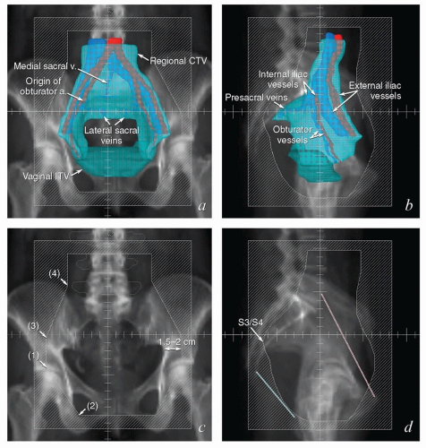 FIGURE 5.9 Paraaortic anatomy and target volume definition. Shown are axial CT slices from the diaphragmatic crus to the bifurcation of the aorta. Selected venous and arterial structures are highlighted in blue and red, respectively. The khaki structures represent the amalgamated contours of 35 PET-positive lymph nodes in 17 patients with cervical cancer. Nodes were mapped to a single patient’s CT scan using deformable image registration; some node contours were edited to more accurately reflect their relationships to vascular structures and avoid overlap with adjacent bowel. Suggested CTV margins are indicated in cyan. (IMA, inferior mesenteric artery; IMV, inferior mesenteric vein.) Most paraaortic nodal metastases are located to the left of the aorta or in the aortocaval spaces. However, metastases can also be found in the right retrocaval space, particularly distal to the right renal vessels. Nodes may be found well to the left of the aorta but are very rarely seen to the right of the vena cava, reflecting the asymmetric fetal development described in Figure 5.1. Therefore, because the aorta is typically at or slightly to the left of midline, the nodes are approximately centered over the vertebral bodies. Distal to approximately L2, the medial margins of the psoas muscles serve as useful guides for the lateral borders of the CTV (d-i). More proximally, the psoas muscle diminishes, but the CTV should still include at least a 1.5- to 2-cm lateral margin on the aorta (a-c).
Stay updated, free articles. Join our Telegram channel
Full access? Get Clinical Tree
 Get Clinical Tree app for offline access

|
