Treatment Simulation
Dimitris N. Mihailidis
Niko Papanikolaou
Introduction
Treatment planning is one of the most crucial processes of radiotherapy, through which the most appropriate way to irradiate the patient is determined. The process is composed by several important steps as follows:
Reproducible patient positioning and immobilization
Accurate identification of the location and shape of the tumor and neighboring critical organs
Selecting the most appropriate beam arrangement
Computing the doses to be delivered and evaluation of resulting dose distributions
Transfer of the treatment planning information to the treatment delivery system
In today’s radiotherapy, three-dimensional (3D) patient anatomy visualization and target definition enable planning to conform the dose to the target volume, delivering as high doses as possible, while avoiding the critical organs. In order to achieve this, a process called treatment simulation is necessary to be performed. In essence, treatment simulation is a combination of, or requires that steps 1 to 3 mentioned above have been performed successfully. There are several ways to perform a simulation, each with a different level of complexity. The most common ones are the following:
When clinical treatment volume can be determined via simple radiographic and fluoroscopic images from a traditional radiotherapy simulator (1), sometimes called the anatomical approach (clinical setup).
When only a limited number of transverse computed tomography (CT) images are used for the target delineation along with radiographic planar images (as above) to complete the treatment planning, sometimes called the traditional approach.
When simulation can be performed on a CT scanner via a special computer software that provides a fully 3D patient representation in the treatment planning position, a process called CT simulation. Then, a complete treatment planning strategy can be designed, a process referred to as virtual simulation (1,2).
Radiotherapy simulation is a very important process on which treatment planning and delivery depend and are based on. The accuracy of the entire radiotherapy treatment can be influenced by the quality of treatment simulation on patient-per-patient basis.
Simulation Methods
Treatment simulation can also be thought of as a “feasibility study” of the patient treatment strategy. Technological advances of medical imaging and computing have brought great improvement to the simulation process and limitless capabilities.
We will describe the three most common methods of radiotherapy simulation today, which strongly depend on the treatment strategy that will be followed for the patient.
Simple Simulation—Anatomical and Traditional Approach
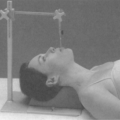
When the patient is necessary to be prepared for treatment in a short amount of time, or there is a simple treatment to be delivered, a conventional simulation can be performed. In this case, a radiographic simulator, which actually operates in both the radiographic and the fluoroscopic mode, is used (Fig. 6.1A, B). It is an apparatus that uses a diagnostic x-ray tube with an image intensifier (Fig. 6.1C), but duplicates that radiotherapy treatment unit in terms of it geometric, mechanical, and optical properties (3,4,5).
The patient is setup and immobilized on the simulator the same way that he/she will be treated on the treatment unit. The clinical borders of the treatment area are marked on the patient skin by the physician and radio-opaque markers are placed on skin on these borders. The selection of the treatment isocenter is done via fluoroscopic imaging of the area, typically with two orthogonal reference views: anterior (AP) and lateral (LAT) (Fig. 6.2). Upon selection of the isocenter, two orthogonal radiographic films (or digital images) are produced for further use and comparison with the treatment setup, and documentation purposes. Then, the beams that will be used for treatment are simulated in order to be geographically optimized, depending on the treatment site, by selecting gantry and collimator angles, treatment field sizes, etc.; all in relationship of externally placed markers and internal bony landmarks. A crucial step is the proper marking of the patient: like the isocenter (as a “3-point” marking) and alignment
skin marks using the simulator laser system in all planes. At the same time, other necessary information is collected to be used for setup and dosimetry such as source-to-surface distances of the simulated treatment fields, patient thickness, determination of the time-set or monitor unit calculation point relative to the isocenter (if half-blocked or heavily blocked fields are used, as in Fig. 6.2), simple contours of the patient surface (with contour-makers) through points of dosimetric interest, and evaluation data for bolus or compensator.
skin marks using the simulator laser system in all planes. At the same time, other necessary information is collected to be used for setup and dosimetry such as source-to-surface distances of the simulated treatment fields, patient thickness, determination of the time-set or monitor unit calculation point relative to the isocenter (if half-blocked or heavily blocked fields are used, as in Fig. 6.2), simple contours of the patient surface (with contour-makers) through points of dosimetric interest, and evaluation data for bolus or compensator.
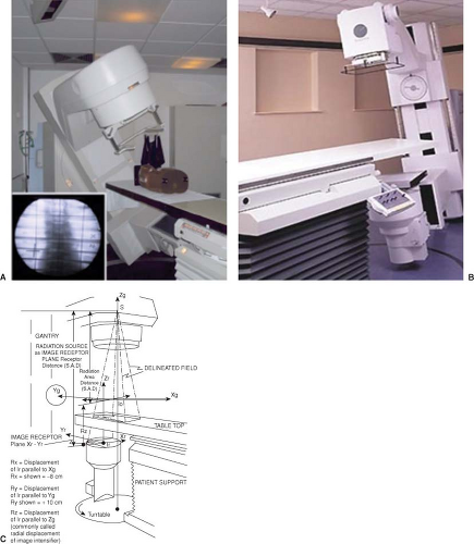 Figure 6.1. Typical radiotherapy simulator. Patient setup represented by a phantom (A), room view (B), and geometric diagram (C). |
Some simulators have a tomographic attachment (simulator-CT) that analyzes and reconstructs the images from the image intensifier using either analog or digital processing (6). However, the quality of the reconstructed
image is inferior to the CT-based simulation. In spite of that, it is adequate for acquiring patient contours and identifying bony landmarks. The simulator CT does provide a volumetric reconstruction of the patient’s anatomy and, as such, could be used as a basic image data set in treatment planning. The reduced spatial resolution of such volumetric imaging renders this technique unsuitable for high precision conformal radiotherapy planning where a series of many thin slices is required for detail volume reconstruction (7,8).
image is inferior to the CT-based simulation. In spite of that, it is adequate for acquiring patient contours and identifying bony landmarks. The simulator CT does provide a volumetric reconstruction of the patient’s anatomy and, as such, could be used as a basic image data set in treatment planning. The reduced spatial resolution of such volumetric imaging renders this technique unsuitable for high precision conformal radiotherapy planning where a series of many thin slices is required for detail volume reconstruction (7,8).
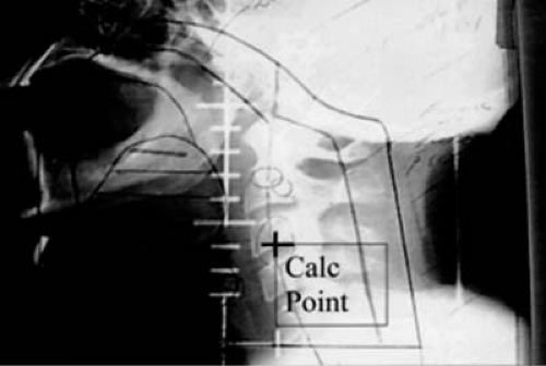 Figure 6.2. Typical simulation portal, lateral view for a head and neck treatment. The blocking is represented by the black marker outlines on the film and the prescription point is denoted as “Calc Point,” which is off-axis related to the half-blocked central axis. |
Interestingly, the concept of simulator CT has recently reemerged and is referred to as cone beam CT (CBCT). Cone beam imaging is currently used in the context of image-guided radiotherapy (IGRT) for daily patient localization and setup verification prior to treatment. Those images could also be used for patient replanning in the context of adaptive radiotherapy, although for the time being this is only a research application. It is expected, however, that once the image quality, imaging dose to the patient, and the speed of replanning improve, CBCT adaptive radiotherapy will become an integral part of advanced radiotherapy.
CBCT imaging can be obtained using the kV imaging system of a linac (Varian, Elekta) or the MV beam itself (Tomotherapy, Siemens). Regardless of the implementation, CBCT is similar to and suffers from the same characteristics as the simulator CT.
Verification Simulation
This is a simulation approach “positioned” between the previous described approach and the virtual simulation that will be described next. This process starts by immobilizing the patient in the treatment planning position with all the necessary devices, this time on the CT scanner flat tabletop. In this case, there is no laser localization system available in the CT room. A standard treatment planning study of the patient will be obtained throughout the clinical area, after radio-opaque markers are placed by the physician on the patient’s skin. The simulation team will need to place “3-point” tattoos or other types of long-lasting markers on the patient’s skin. For CT purposes, the “3-point” locations and the treatment area borders will be visible on the CT images. Patient scans are typically obtained in an axial mode, 3- to 5-mm slice thickness. Smaller slice thickness can be used for small areas, when higher resolution and accuracy is necessary.
The CT images are reviewed and then imported to a treatment planning system where a computer simulation will be done off-line. The physician will define the volumes of interest and the isocenter might be adjusted to accommodate the target volume extensions. The coordinates of the treatment isocenter can be referenced to the original “3-point” location marked in the CT room. Next, the remaining treatment planning process is completed and the plan gets finalized. Two orthogonal (AP & LAT), digitally reconstructed radiographs (DRRs) (9,10) at the original CT point and the new isocenter will be produced at this point (Fig. 6.3). DRRs of the treatment fields will also be produced.
A verification simulation is scheduled in the conventional simulator, where the patient is immobilized and setup again in the treatment planning position. The patient then is simulated according to the approved treatment plan. A sample simulation form is shown in Figure 6.4, where all the appropriate shifts from the original CT marks to the final isocenter are implemented. An orthogonal set of setup ports, first at the original CT point (“3-point” mark) and then at the treatment isocenter will assure the proper localization, when compared to the DRRs at the same locations. The patient will be marked appropriately to insure reproducibility of setup during treatment. Further on, additional ports of the treatment fields can be obtained to increase the accuracy of the simulation setup and for documentation purposes. The orthogonal ports and treatment ports will be compared to portal images or portal films in the treatment room, especially at the first day of treatment. A diagram of the verification simulation process is shown in Figure 6.5A.
CT Simulator and Virtual Simulation
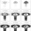
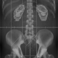
This is an exciting development in the area of simulation because it converts a CT (or other scanning modality) scanner into a simulator (1,2,11,12,13). Both patient and treatment units are virtual, the patient being represented by CT images and the treatment unit by model beam geometry and expected dose distributions. The simulation film is replaced by the DRRs. The DDRs are generated from the CT scan data by mapping average CT values computed along lines drawn from a “virtual source” to the location of the “virtual film.” A DRR is essentially a calculated port film that serves as a simulator film, which contains all the useful anatomical information of the patient (Fig. 6.6). A dedicated radiation therapy CT scanner, with
the above described virtual simulation software and simulation accessories (e.g., flat tabletop, immobilization devices, etc.), is called a CT simulator (Fig. 6.7A). In addition, CT simulators are equipped with high precision movable laser systems to mark the isocenter location on the patient during the virtual simulation process. The laser system is mounted on fixed pedestals on the floor and ceiling as shown in Figure 6.7B.
the above described virtual simulation software and simulation accessories (e.g., flat tabletop, immobilization devices, etc.), is called a CT simulator (Fig. 6.7A). In addition, CT simulators are equipped with high precision movable laser systems to mark the isocenter location on the patient during the virtual simulation process. The laser system is mounted on fixed pedestals on the floor and ceiling as shown in Figure 6.7B.
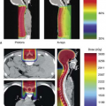
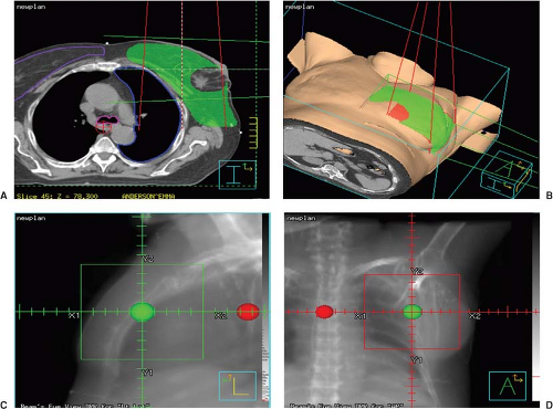 Figure 6.3. Breast patient computed tomography (CT) image with two orthogonal reference fields on the treatment isocenter-GREEN point (A), three-dimensional (3D) reconstruction of the patient imaged area with the reference field (B), LAT-reference field to the treatment isocenter (C), AP-reference filed to the isocenter (D). The RED point is the original CT point. |
Modern radiotherapy CT simulators are based on the most recent CT scanner technology with multi-slice (multi-detector) detector technology, axial and helical scanning mode capabilities, rapid CT acquisition time, and high image quality performance and wide bore (>75 cm diameter) to accommodate the patient immobilization devices (Fig. 6.8). Further on, an option called gating allows the scanner to perform “motion-correlated” scanning, a process called 4DCT (the 4th being the time information), useful for accurate treatment planning on moving anatomy (e.g., respiratory motion in lung). The standard linear accelerator (linac) requirements, for example, large weight capability (up to 450–600 lb load), small sag (<2 mm), and hard tabletop, apply for CT simulators also.
A diagram that describes the CT simulation and virtual simulation processes is shown in Figure 6.5B.
CT Simulation Process
The patient is immobilized on the CT table and in the treatment planning position. At this initial stage, all special immobilization devices (e.g., head and neck masks, pelvic shells, breast boards, etc.) are required to be constructed and/or utilized, in order to be included in the CT image study of the patient. These devices can be indexed on the CT tabletop, the same way that later on will be indexed on the linac treatment table (Fig. 6.9A–C). Additional planning modifiers, such as skin bolus, are also required to be included. The borders of the clinical area marked by the physician on the patient can be outlined with CT radio-opaque markers (Fig. 6.9C). Sometimes, initial reference skin marks are placed in the middle of the clinical treatment area. The CT movable lasers are used to define and mark the CT reference point on the patient.
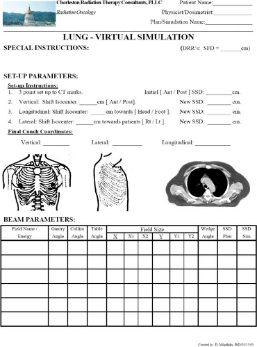 Figure 6.4. Sample in-house simulation form for lung setup. Note the setup instructions and appropriate shift information from the “3-point” computed tomography (CT) mark to the treatment isocenter. Detail information on the treatment fields are entered in the table below. This firm can be used for verification simulation also. |
A set of anterior and lateral topograms (“scout views”) will assist the patient alignment on the CT table. The patient will be scanned based on a preset protocol according to the disease site and the images will be stored for virtual simulation, while the patient remains on the CT table.
Virtual Simulation Process
There are three tasks that pertain to virtual simulation. First is the treatment isocenter localization, which is typically placed at the geometric center of the treatment volume. The second is the target and critical structures volume delineation. The third is to determine the treatment beam parameters via beam’s-eye-view (BEVs) (14) using DRRs, including gantry, collimator and couch angles, field sizes, shielding block, etc. This last part can also be performed at a later time during the treatment planning and isodose computation process.
Related posts:

Stay updated, free articles. Join our Telegram channel

Full access? Get Clinical Tree


