Spatial Orientation in Flight
A. J. Parmet
W. R. Ercoline
Appearances often are deceiving.
—Aesop
A major purpose of aerospace medicine as a specialty is the prevention of aircraft accidents and injuries. The therapy for these conditions continues to have poor results. Injuries are often disabling and fatality rates are higher in spatial orientation accidents than other types of accidents with a 90% fatality rate (1). Only prevention truly saves lives. From the earliest days of aviation, almost all accidents were attributable to human factors. During the First World War, survival of pilots was often measured in weeks, yet combat had little to do with their deaths. Most losses were due to accidents and almost all accidents were due to spatial disorientation (SD) (2). Currently, most accidents are still overwhelmingly due to human factors and a major contributor to those accidents worldwide is SD. It is essential for the understanding of spatial orientation to comprehend how the human body interacts and interprets the environment of flight in order to provide control and prevent loss of orientation that can lead to an accident.
MECHANICS
Operators of today’s and tomorrow’s air and space vehicles must understand clearly the terminology and physical principles relating to the motions of their aircraft so they can fly with precision and effectiveness. These crewmembers also must have a working knowledge of the structure and function of the various mechanical and electrical systems of which their craft is comprised. This will help them understand the performance limits of their machines and facilitate troubleshooting and promote safe recovery when the machines fail in flight. So, too, must practitioners of aerospace medicine understand certain basic definitions and laws of mechanics so that they can analyze and describe the environment to which the flyer is exposed. In addition, the aeromedical professional must be familiar with the physiologic bases and operational limitations of the flyer’s orientation mechanisms. This understanding is necessary to enable the physician or physiologist to speak intelligently and credibly with aircrew about SD, and to enable them to contribute significantly to investigations of aircraft mishaps in which SD may be implicated.
Motion
We shall discuss two types of physical motion: linear motion or motion of translation, and angular motion or motion of rotation. Linear motion can be further categorized as rectilinear, meaning motion in a straight line, or curvilinear, meaning motion in a curved path. Both linear motion and angular motion comprise an infinite variety of subtypes, or motion parameters, based on successive derivatives of linear or angular position with respect to time. The most basic of these motion parameters, and the most useful, are displacement, velocity, acceleration, and jerk. Table 6-1 classifies linear and angular motion parameters and their symbols, and units serve as an outline for the following discussions of linear and angular motion.
Linear Motion
The basic parameter of linear motion is linear displacement. The other parameters: velocity, acceleration, and jerk are derived from the concept of displacement. Linear displacement, x, is the distance and direction of the object under consideration from some reference point; as such, it is a vector quantity, having both magnitude and direction. The position of an aircraft located at 25 nautical miles on the 150-degree radial of the San Antonio VORTAC, for example, describes completely the linear displacement
of the aircraft from the navigational facility serving as the reference point. The meter (m), however, is the unit of linear displacement in the International Systems of Units (SI), and will eventually replace other units of linear displacement such as feet, nautical miles, and statute miles.
of the aircraft from the navigational facility serving as the reference point. The meter (m), however, is the unit of linear displacement in the International Systems of Units (SI), and will eventually replace other units of linear displacement such as feet, nautical miles, and statute miles.
TABLE 6-1 | ||||||||||||||||||||||||||||||||||||||
|---|---|---|---|---|---|---|---|---|---|---|---|---|---|---|---|---|---|---|---|---|---|---|---|---|---|---|---|---|---|---|---|---|---|---|---|---|---|---|
| ||||||||||||||||||||||||||||||||||||||


 , v,
, v, 
 ,
, 
 ,
,  ,
,  ,
, 
 ,
,  ,
, 
When linear displacement is changed during a period of time, another vector quantity, linear velocity, occurs. The formula for calculating the mean linear velocity, v, during time interval, Δt, is as follows:
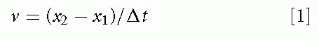
where x1 is the initial linear displacement and x2 is the final linear displacement. An aircraft that travels from San Antonio, Texas to New Orleans, Louisiana in 1 hour, for example, moves with a mean linear velocity of 434 knots (nautical miles per hour) on a true bearing of 086 degrees. Statute miles per hour and feet per second are other commonly used units of linear speed, the magnitude of linear velocity; meters per second (m/s), however, is the SI unit and is preferred. Velocity is the first derivative of displacement with respect to time, dx/dt.
When the linear velocity of an object changes over time, the difference in velocity, divided by the time required for the moving object to make the change, gives its mean linear acceleration, a. The following formula:
where v1 is the initial velocity, v2 is the final velocity, and Δt is the elapsed time is used to calculate the mean linear acceleration, which, like displacement and velocity, is a vector quantity with magnitude and direction. Acceleration is therefore the rate of change of velocity, just as velocity is the rate of change of displacement. The SI unit for the magnitude of linear acceleration is meters per second squared (m/s2). Consider, for example, an aircraft that accelerates from a complete stop to a velocity of 100 m/s in 5 seconds: the mean linear acceleration is (100 m/s – 0 m/s)/5 s or 20 m/s2. The instantaneous linear acceleration is the second derivative of displacement or the first derivative of velocity, d2x/dt2, or dv/dt, respectively.
A very useful unit of acceleration is g, which for our purposes is equal to the constant go, the amount of acceleration exhibited by a free-falling body near the surface of the Earth—9.81 m/s2 or 32.2 ft/s2 (see also Chapter 4). To convert values of linear acceleration given in m/s2 into g units, simply divide by 9.81. In the previous example in which an aircraft accelerates at a mean rate of 20 m/s2, one divides 20 m/s2 by 9.81 m/s2 per g (i.e., one Earth gravity or “g” is 9.81 m/s2 or 32.2 ft/s2—see Equation 16) to obtain 2.04 g. NOTE: In this text we refer to the ratio of acceleration to the acceleration of a free falling body with the letter “g.” Some texts use the upper case G, which is also used in physics texts to represent the universal gravitational force constant. We decided to use the lower case.
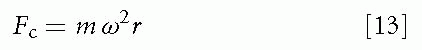
A special type of linear acceleration, radial or centripetal acceleration, results in curvilinear, usually circular, motion. This acceleration acts along the line represented by the radius of the curve and is directed toward the center of the curvature. Its effect is a continuous redirection of the linear velocity, in this case called tangential velocity, of the object subjected to the acceleration. Two examples of this type of linear acceleration are when an aircraft pulls out of a dive after firing on a ground target or flies a circular path during acrobatic maneuvering. The value of the centripetal acceleration, ac, can be calculated if one knows the tangential velocity, vt, and the radius, r, of the curved path followed:
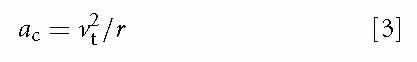
For example, the centripetal acceleration of an aircraft traveling at 300 m/s (˜600 knots) and having a radius of turn of 1,500 m can be calculated. Dividing (300 m/s)2 by 1,500 m gives a value of 60 m/s2, which, when divided by 9.81 m/s2 per g, comes out to 6.12 g.
This concept of acceleration due to circular motion can also be applied to the space shuttle when it orbits the Earth. As the shuttle moves along its orbit with a predetermined translational velocity it is simultaneously falling toward the Earth at the rate determined by the gravitational pull between the Earth and the shuttle. There is a constant radial acceleration, which is equal and opposite to the acceleration that would be experienced if one could remain motionless at that same altitude. Hence, to the person in the shuttle, the net effect is zero g. This does not mean that there is no gravity or acceleration. It just means the effect of all accelerations is zero (or close to it).
One can go another step in the derivation of linear motion parameters by obtaining the rate of change of
acceleration. This quantity, j, is known as linear jerk. Mean linear jerk is calculated as follows:
acceleration. This quantity, j, is known as linear jerk. Mean linear jerk is calculated as follows:
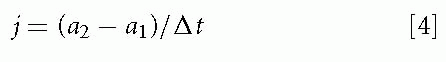
where a1 is the initial acceleration, a2 is the final acceleration, and Δt is the elapsed time.
Instantaneous linear jerk is the third derivative of linear displacement or the first derivative of linear acceleration with respect to time that is d3x/dt3 or da/dt, respectively. Although the SI unit for jerk is m/s3, it is generally more useful to speak in terms of g-onset rate, measured in g per second (g/s).
Angular Motion
Although we touched upon angular motion with the shuttle example earlier, it is instructional to discuss in more detail some of the nuances of angular motion. The derivation of the parameters of angular motion follows in a manner parallel to the scheme used to derive the parameters of linear motion. The basic parameter of angular motion is angular displacement. For an object to be able to undergo angular displacement it must be polarized, that is, it must have a front and back, so that it can face or be pointed in a particular direction. A simple example of angular displacement is seen in a person facing east. In this case, the individual’s angular displacement is 90-degree clockwise from the reference direction, which is north. Angular displacement, symbolized by θ (theta), is generally measured in degrees, revolutions (1 revolution = 360 degrees), or radians (1 radian = 1 revolution) 2π or approximately 57.3 degrees. The radian is a particularly convenient unit to use when dealing with circular motion (e.g., motion of a centrifuge) because it is necessary only to multiply the angular displacement of the system, in radians, by the length of the radius to find the value of the linear displacement along the circular path. The radian is the angle subtended by a circular arc the same length as the radius of the circle.
Angular velocity, ω (omega), is the rate of change of angular displacement. The mean angular velocity occurring in a time interval, delta Δt, is calculated as follows:
where θ1 is the initial angular displacement and θ2 is the final angular displacement.
Instantaneous angular velocity is dθ/dt. As an example of angular velocity, consider the standard-rate turn of instrument flying, in which a heading change of 180 degrees is made in 1 minute. Then ω = (180 degrees – 0 degrees)/60 s or 3 degrees/s. This angular velocity can also be described as 0.5 revolutions per minute (rpm) or as 0.052 radians per second (rad/s) (3 degrees/s divided by 57.3 degrees/rad). The fact that an object may be undergoing curvilinear motion during a turn in no way affects the calculation of its angular velocity: an aircraft being rotated on the ground on a turntable at a rate of half a turn per minute has the same angular velocity as one flying a standard rate instrument turn (3 degrees/s) in the air at 300 knots. Because radial or centripetal linear acceleration results when rotation is associated with a radius from the axis of rotation, a formula for calculating the centripetal acceleration, ac, from the angular velocity, ω, and the radius, r, is often useful:
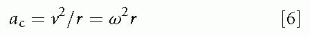
where ω is the angular velocity in radians/s. One can convert readily to the formula for centripetal acceleration in terms of tangential velocity if one remembers the following:
To calculate the centrifuge having a 10-m arm and turning at 30 rpm, Equation 6 is used after first converting 30 rpm to π (or 3.14) radians/s. Squaring the angular velocity and multiplying by the 10-m radius, a centripetal acceleration of 10π2 m/s2 or 10.1 g is obtained.
The rate of change in angular velocity is angular acceleration, α(alpha). The mean angular acceleration is calculated as follows:
where ω1 is the initial angular velocity, ω2 is the final angular velocity, and Δt is the time interval over which angular velocity changes.
α, d2θ/dt2, and dω/dt can be used to symbolize instantaneous angular acceleration, the second derivative of angular displacement or the first derivative of angular velocity with respect to time. If a figure skater is spinning at 6 revolutions/s (2,160 degrees/s or 37.7 rad/s) and then comes to a complete stop in 2 seconds, the rate of change of angular velocity, or angular acceleration, is (37.7 rad/s)/2 s or -18.9 rad/s2.
Although not commonly used in aerospace medicine, another parameter derived from angular displacement is angular jerk, the rate of change of angular acceleration. Its description is completely analogous to that for linear jerk, but angular rather than linear symbols and units are used.
Force, Inertia, and Momentum
Generally, it is not the linear and angular motions themselves, but the forces and torques which result in or appear to result from linear and angular velocity changes that stimulate or compromise the crewmember’s physiologic mechanisms.
Force and Torque
Force is an influence that produces, or tends to produce, linear motion or changes in linear motion; it is a pushing or pulling action. Torque produces, or tends to produce, angular motion or changes in angular motion; it is a twisting or turning action. The SI unit of force is the newton (N). Torque has dimensions of force and length because torque is applied as a force at a certain distance from the center of rotation. The newton-meter (N-m) is the SI unit of torque.
Mass and Rotational Inertia
Newton’s law of acceleration states the following:
where F is the force applied to an object, m is the mass of the object, and a is linear acceleration. To describe
the analogous situation pertaining to angular motion, the following equation is used:
the analogous situation pertaining to angular motion, the following equation is used:
where M is unbalanced torque (for moment) applied to the rotating object, J is rotational inertia (moment of inertia) of the object, and α represents the angular acceleration.
The mass of an object is therefore the ratio of the force acting on the object to the acceleration resulting from the force. Mass, therefore, is a measure of the inertia of an object—its resistance to being accelerated. Similarly, rotational inertia is the ratio of the torque acting on an object to the angular acceleration resulting from that torqueagain, a measure of resistance to acceleration. The kilogram (kg) is the SI unit of mass and is equivalent to 1 N/(m/s2). The SI unit of rotational inertia is merely the N m/(radian/s2).
Because F = ma, the centripetal force, Fc, needed to produce a centripetal acceleration, ac, of a mass, m, can be calculated as follows:
Therefore, from Equation 3:
or from Equation 6:
where vt is tangential velocity, ω represents angular velocity, and r is the radius of motion. Newton’s law of action and reaction, which states that for every force applied to an object there is an equal and opposite reactive force exerted by that object, provides the basis for the concept of inertial force. Inertial force is an apparent force opposite in direction to an accelerating force and equal to the mass of the object times the acceleration. An aircraft exerting an accelerating forward thrust on its pilot causes an inertial force, the product of the pilot’s mass and the acceleration, to be exerted on the back of the seat by the pilot’s body. Similarly, an aircraft undergoing positive centripetal acceleration as a result of lift generated in a turn causes the pilot’s body to exert inertial force on the bottom of the seat. More important, however, are the inertial forces exerted on the pilot’s blood and organs of equilibrium because physiologic effects result directly from such forces.
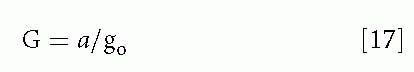
At this point it is appropriate to introduce G, which is used to measure the strength of the gravitoinertial force environment. (NOTE: G should not be confused with G, the symbol for the universal gravitational constant, which is equal to 6.70 × 10⁻¹¹ N m2/ kg2.) Strictly speaking, G is a measure of relative weight:
where w is the weight observed in the environment under consideration and wo is the normal weight on the surface of the Earth. In the physical definition of weight,
and
where m is mass, a is the acceleratory field (vector sum of actual linear acceleration plus an imaginary acceleration opposite the force of gravity), and go is the standard value of the acceleration of gravity (9.81 m/s2). Therefore, a person having a mass of 100 kg would weigh 100 kg times 9.81 m/s2 or 981 N on Earth (although conventional spring scales would read “100 kg”). At some other location or under some other acceleratory condition, the same person could weigh twice as much (1,962 N) and cause a scale to read “200 kg.” The person would then be in a 2-G environment, or, if that person were in an aircraft, he or she would be said to be “pulling” 2 G. Consider also that because
G = w/wo = ma/mgo
then,
Therefore, the ratio between the ambient acceleratory field (a) and the standard acceleration (go) can also be represented in terms of G.
Therefore, g is used as a unit of acceleration (e.g., ac = 8 g), and the dimensionless ratio of weights, G, is reserved for describing the resulting gravitoinertial force environment (e.g., a force of 8 G or an 8-G load). When in the vicinity of the surface of the Earth, one feels a G force equal to 1 G in magnitude directed toward the center of the Earth. If one also sustains a G force resulting from linear acceleration, the magnitude and direction of the resultant gravitoinertial G force can be calculated by adding vectorially the 1-G gravitational force and the inertial G force. An aircraft pulling out of a dive with a centripetal acceleration of 3 g, for example, would exert 3 G of centrifugal force. At the bottom of the dive, the pilot would experience the 3-G centrifugal force in line with the 1-G gravitational force, for a total of 4 G directed toward the floor of the aircraft. If the pilot could continue the circular flight path at a constant airspeed, the G force experienced at the top of the loop would be 2 G because the 1-G gravitational force would subtract from the 3-G inertial force. Another common example of the addition of gravitational G force and inertial G force occurs during the application of power on takeoff or on a missed approach. If the forward acceleration is 1 g, the inertial force is 1 G directed toward the tail of the aircraft. The inertial force adds vectorially to the 1-G force of gravity, directed downward, to provide a resultant gravitoinertial force of 1.414 G pointing 45 degrees down from the aft direction.
Just as inertial forces oppose acceleration forces, so do inertial torques oppose acceleratory torques. No convenient derived units exist, however, for measuring inertial torque; specifically, there is no such thing as angular G.
Momentum
To complete this discussion of linear and angular motion, the concepts of momentum and impulse must be introduced. Linear momentum is the product of mass and linear velocity—m and v. Angular momentum is the product of rotational inertia and angular velocity—Jω. Momentum is a
quantity that a translating or rotating body conserves, that is, an object cannot gain or lose momentum unless it is acted on by a force or torque. A translational impulse is the product of force, F, and the time over which the force acts on an object, Δt (delta t), and is equal to the change in linear momentum imparted to the object. Therefore:
quantity that a translating or rotating body conserves, that is, an object cannot gain or lose momentum unless it is acted on by a force or torque. A translational impulse is the product of force, F, and the time over which the force acts on an object, Δt (delta t), and is equal to the change in linear momentum imparted to the object. Therefore:
where v1 is the initial linear velocity and v2 is the final linear velocity.
When dealing with angular motion, a rotational impulse is defined as the product of torque, M, and the time over which it acts, Δt. A rotational impulse is equal to the change in angular momentum. Therefore,
where ω1 is the initial angular velocity and ω2 is the final angular velocity.
The above relations are derived from the law of acceleration, as follows:
F = ma
M = Jα
because a = (v2 – v1)/Δt and α = (ω2 – ω1)/Δt
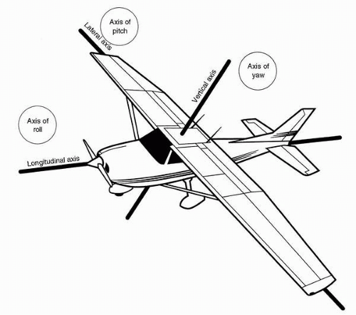 FIGURE 6-1 Axes of linear and angular aircraft motions. Linear motions are longitudinal, lateral, and vertical, and angular motions are roll, pitch, and yaw. |
Directions of Action and Reaction
A number of conventions have been used in aerospace medicine to describe the directions of linear and angular displacement, velocity, and acceleration and of reactive forces and torques. The more commonly used of those conventions will be discussed in the following sections.
Vehicular Motions
Because space is three-dimensional, linear motions in space are described by reference to three linear axes and angular motions by reference to three angular axes. In aviation, it is customary to speak of the longitudinal (foreaft), lateral (right-left), and vertical (up-down) linear axes and the roll, pitch, and yaw angular axes, as shown in Figure 6-1.
Most linear accelerations in aircraft occur in the vertical plane defined by the longitudinal and vertical axes, because thrust is usually developed along the former axis and lift is usually developed along the latter axis. However, that is changing. Aircraft capable of vectored thrust are now operationally used such as the F-22 and vectored-lift aircraft such as the CV-22 (tilt-wing rotorcraft) have been in operation for several years. This will create an even more threatening environment for SD.
Most angular accelerations in aircraft occur in the roll plane (perpendicular to the roll axis) and, to a lesser extent, in the pitch plane. Angular motion in the yaw plane is very limited in normal flying, although it does occur during spins and several other acrobatic maneuvers. Certainly, aircraft and space vehicles of the future can be expected to operate with considerably more freedom of both linear and angular motion than do those of the present.
Physiologic Acceleration and Reaction Nomenclature
Figure 6-2 depicts a practical system for describing linear and angular accelerations acting on humans (3). This system is used extensively in aeromedical scientific writing. In this system, a linear acceleration of the type associated with a conventional takeoff roll is in the +ax direction, that is, it is a +ax acceleration. Braking to a stop during a landing roll results in −ax acceleration. Radial acceleration, the type usually developed during air combat maneuvering, is +az acceleration: foot-to-head. The right-hand rule for describing the relationships between three orthogonal axes aids recall of the positive directions of ax, ay, and az accelerations in this particular system: if one lets the forward-pointing index finger of the right hand represent the positive x-axis and the left-pointing middle finger of the right hand represent the positive y-axis, the positive z-axis is represented by the upward-pointing thumb of the right hand. A different right-hand rule, however, is used in another convention, one for describing vehicular coordinates. In that system, +ax is noseward acceleration, +ay is to the right, and +az is floorward; an inverted right hand illustrates that set of axes.
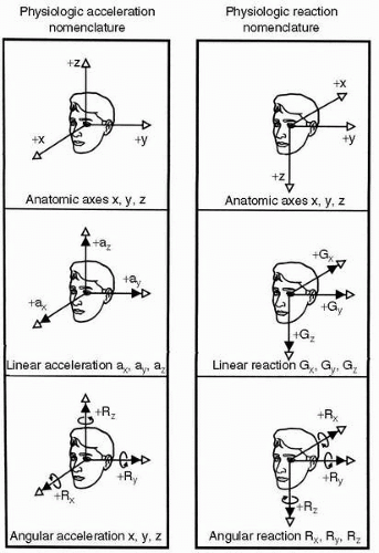 FIGURE 6-2 System for describing accelerations and inertial reactions in humans. (Adapted from Hixson WC, Niven JI, Correia MJ. Kinematics nomenclature for physiological accelerations, with special reference to vestibular applications. Monograph 14. Pensacola, Florida: Naval Aerospace Medical Institute, 1966.) |
The angular accelerations, αx, αy, and αz, are roll, pitch, and yaw accelerations, respectively, in the system shown in Figure 6-2. Note that the relations between the positive x-axis, y-axis, and z-axis are identical to those for linear accelerations. The direction of positive angular displacement, velocity, or acceleration is described by another right-hand rule, wherein the flexed fingers of the right hand indicate the direction of angular motion corresponding to the vector represented by the extended, abducted right thumb. Therefore, in this system, a right roll results from +αx acceleration, a pitch down results from +αy acceleration, and a left yaw results from +αz acceleration. Again, it is important to be aware of the inverted right-hand coordinate system commonly used to describe angular motions of vehicles. In that convention, a positive roll acceleration is to the right, positive pitch is upward, and positive yaw is to the right. Our system describes the motion of the vehicle occupant.
The nomenclature for the direction of gravitoinertial (G) forces acting on humans is also illustrated in Figure 6-2. Note that the relation of these axes to each other follows a backward, inverted, right-hand rule. In the illustration convention, +αx acceleration results in +Gx inertial force, and +αz acceleration results in +Gz force. This correspondence of polarity is not achieved on the y-axis, however, because +ay acceleration results in −Gy force. If the +Gy direction were reversed, full polarity correspondence could be achieved between all linear accelerations and all reactive forces, and that convention has been used by some authors. An example of the usage of the symbolic reaction terminology would be: “An F-16 pilot must be able to sustain +9.0 Gz without losing vision or consciousness.”
The “eyeballs” nomenclature is another useful set of terms for describing gravitoinertial forces. In this system, the direction of the inertia reaction of the eyeballs, when the head is subjected to an acceleration, is used to describe the direction of the inertial force. The equivalent expressions, “eyeballs-in acceleration” and “eyeballs-in G force,” leave little room for confusion about either the direction of the applied acceleratory field or the resulting gravitoinertial force environment.
Inertial torques can be described conveniently by means of the system shown in Figure 6-2, in which the angular reaction axes are the same as the linear reaction axes. The inertial reactive torque resulting from +αx (right roll) angular acceleration is +Rx and +αz (left yaw) results in +Rz; however, +αy (downward pitch) results in −Ry. This incomplete correspondence between acceleration and
reaction coordinate polarities again results from the mathematical tradition of using right-handed coordinate systems.
reaction coordinate polarities again results from the mathematical tradition of using right-handed coordinate systems.
It should be apparent from all this that the potential for confusing the audience when speaking or writing about acceleration and inertial reaction is great enough to make it a virtual necessity to describe the coordinate system being used. For most applications, the “eyeballs” convention is perfectly adequate.
VISUAL ORIENTATION
Vision is by far the most important sensory modality subserving spatial orientation, especially so in moving vehicles such as aircraft. Without it, flight as we know it would be impossible, whereas this would not be necessarily the case in the absence of the vestibular or other sensory systems that provide orientation information. Certain special features of visual orientation deserve mention. First, there are two separate visual orientation systems that have two distinct functions: object recognition and spatial orientation. Knowledge of these systems is extremely important to help in understanding visual illusions in flight and appreciate the difficulties inherent in using flight instruments for spatial orientation. Second, visual and vestibular orientation information is integrated at very basic neural levels. For that reason, SD is frequently not amenable to correction by higher-level neural processing.
Anatomy and the Visual System
General
The retina, an evaginated portion of the embryonic brain, consists of an outer layer of pigmented epithelium and an inner layer of neural tissue. Contained within the latter layer are the sensory rod and cone cells, the bipolar and horizontal cells that comprise the intraretinal afferent pathway from the rods and cones, and the multipolar ganglion cells, the axons of which are the fibers of the optic nerve. The cones, which number approximately 7 million in the human eye, have a relatively high threshold to light energy. They are responsible for sharp visual discrimination and color vision. The rods, of which there are more than 100 million, are much more sensitive to light than the cones; they produce the ability to see in twilight and at night. In the macula, near the posterior pole of the eye, the cone population achieves its greatest density; within the central macula, the fovea centralis—a small pit totally comprises tightly packed slender cones—provides the sharpest visual acuity and is the anatomic basis for foveal, or central, vision. The remainder of the eye is capable of far less visual acuity and subserves paracentral and peripheral vision.
Having dendritic connections with the rods and cones, the bipolar cells provide axons that synapse with the dendrites or cell bodies of the multipolar ganglion cells, whose axons in turn course parallel to the retinal surface and converge at the optic disk. Emerging from the eye as the optic nerve, they meet their counterparts from the opposite eye in the optic chiasm and then continue in one of the optic tracts, most likely to terminate in a lateral geniculate body, but possibly in a superior colliculus or the pretectal area. Second-order neurons from the lateral geniculate body comprise the geniculocalcarine tract, which becomes the optic radiation and terminates in the primary visual cortex, the striate area of the occipital cortex (area 17). In the visual cortex, the retinal image is represented as a more or less point-to-point projection from the lateral geniculate body, which receives a similar topographically structured projection from both retinae. The lateral geniculate and the primary visual cortex are therefore structurally and functionally suited for the recognition and analysis of visual images. The superior colliculi project to the visual association areas (areas 18 and 19) of the cerebral cortex through the pulvinar, and eventually to the motor nuclei of the extraocular muscles and muscles of the neck, and appear to provide a pathway for certain gross ocular reflexes of visual origin. Fibers entering the pretectal area are involved in pupillary reflexes. In addition, most anatomic and physiologic evidence indicates that information from the occipital visual association areas, parietal cerebral cortex, and frontal eye movement area (area 8) is relayed through the paramedian pontine reticular formation to the nuclei of the cranial nerves innervating the extraocular muscles. Through this pathway and perhaps others involving the superior colliculi, saccadic (fast) and pursuit (slow) eye movements are initiated and controlled. Third- and fourth-order neurons are immensely complex with some neurons having more than a thousand synapses per cell, and their projections become diffusely integrated within the entire nervous system.
Visual-Vestibular Convergence
Vision in humans and other primates is highly dependent on cerebral cortical structure and function, whereas vestibular orientation primarily involves more primitive anatomic structures. Yet visual and vestibular orientational processes are by no means independent. We know that visually perceived motion information and probably other visual orientational data reach the vestibular nuclei in the brainstm (4,5), but it appears that a major integration of visual and vestibular orientational information is first accomplished in the cerebral cortex.
The geniculostriate projection system, responsible for conscious visual awareness, is divided both anatomically and functionally into two parts: the parvocellular layers of the lateral geniculate body (the “parvo” system) and the magnocellular layers (the “magno” system). These systems remain partly segregated in the primary visual cortex, undergo further segregation in the visual association cortex, and ultimately terminate in the temporal and parietal lobes, respectively. The parvo system neurons have smaller, more centrally located receptive fields that exhibit high spatial resolution (acuity), and they respond well to color; they do not, however, respond well to rapid motion or high
flicker rates. The magno cells, by comparison, have larger receptive fields and respond better to motion and flicker, but are relatively insensitive to color differences. Magno neurons generally exhibit poorer spatial resolution, although they seem to respond better than parvo neurons at low luminance contrasts. In general, the parvo system is better at detecting small, slowly moving, colored targets located near the center of the visual field, whereas the magno system is more capable of processing rapidly moving and optically degraded stimuli across larger regions of the visual field.
flicker rates. The magno cells, by comparison, have larger receptive fields and respond better to motion and flicker, but are relatively insensitive to color differences. Magno neurons generally exhibit poorer spatial resolution, although they seem to respond better than parvo neurons at low luminance contrasts. In general, the parvo system is better at detecting small, slowly moving, colored targets located near the center of the visual field, whereas the magno system is more capable of processing rapidly moving and optically degraded stimuli across larger regions of the visual field.
What is important about these two components of the geniculostriate system is that the parvo system projects ventrally to the inferior temporal areas, which are involved in visual search, pattern recognition, and visual object memory, whereas the magno system projects dorsally to the posterior parietal and superior temporal areas, which are specialized for motion information processing. The cerebral cortical areas to which the parvo system projects receive virtually no vestibular afferents; the areas to which the magno system projects, on the other hand, receive significant vestibular and other sensory inputs, and are believed to be involved to a greater extent in maintaining spatial orientation.
The posterior parietal region projects heavily to cells of the pontine nuclei, which in turn provide the mossy-fiber visual input to the cerebellar cortex. Through the accessory optic and central tegmental tracts, visual information also reaches the inferior olives, which provide climbing fiber input to the cerebellar cortex. The cerebellar cortex, specifically the flocculonodular lobe and vermis, also receives direct mossyfiber input from the vestibular system. Therefore, cerebellar cortex is another area of very strong visual-vestibular convergence. Furthermore, the cerebellar Purkinje cells have inhibitory connections in the vestibular nuclei and possibly even in the vestibular end organs; so visual-vestibular interactions mediated by the cerebellum also occur at the level of the brainstem, and maybe even peripherally.
Finally, there is a confluence of visual and vestibular pathways in the paramedian pontine reticular formation. Integration of visual and vestibular information in the cerebellum and brainstem appears to allow visual control of basic equilibratory reflexes of vestibular origin. As might be expected, there are also afferent vestibular influences on visual system nuclei; these influences have been demonstrated in the lateral geniculate body and superior colliculus.
Visual Information Processing
Primary control of the human ability to move and orient ourselves in three-dimensional space is mediated by the visual system, as exemplified by the fact that individuals without functioning vestibular systems (“labyrinthine defectives”) have virtually no problems with spatial orientation unless they are deprived of vision. The underlying mechanisms of visual orientation-information processing are revealed by receptive-field studies, which have been accomplished for the peripheral retina, relay structures, and primary visual cortex. Basically, these studies show that there are several types of movement-detecting neurons and that these neurons respond differently to such features as the direction of movement, velocity of movement, size of the stimulus, its orientation in space, and the level of illumination (6).
As evidenced by the division of the primate geniculostriate system into two separate functional entities, however, vision must be considered as two separate processes. Some researchers emphasize the role of the ventral (parvo) system in object recognition (the “what” system) and that of the dorsal (magno) system in spatial orientation (the “where” system); others categorize the difference in terms of form (occipitotemporal) versus motion (occipitoparietal) processing. A recent theory suggests that the dorsal system is primarily involved in processing information in peripersonal (near) space during reaching and other visuomotor activity, whereas the ventral system is principally engaged in visual scanning in extrapersonal (far) visual space (7). In the present discussion, we shall refer to the systems as the “focal” and “ambient” visual systems, respectively, subserving the focal and ambient modes of visual processing. Certain aspects of yet another visual process, the one responsible for generating eye movements, will also be described.
Focal Vision
Liebowitz and Dichgans (8) have provided a very useful summary of the characteristics of focal vision:
[The focal visual mode] is concerned with object recognition and identification and in general answers the question of “what.” Focal vision involves relatively fine detail (high spatial frequencies) and is correspondingly best represented in the central visual fields. Information processed by focal vision is ordinarily well represented in consciousness and is critically related to physical parameters such as stimulus energy and refractive error.
Focal vision uses the central 30 degrees or so of the visual field. Although it is not primarily involved with orienting the individual in the environment, it certainly contributes to the internal viewpoint, derived from judgments of distance and depth and those obtained from reading flight instruments. Tredici (9) categorized the visual cues to distance and depth as monocular or binocular. There are eight monocular cues: (a) size constancy, the size of the retinal image in relation to known and comparative sizes of objects; (b) shape constancy, the shape of the retinal image in relation to the known shape of the object (e.g., the foreshortening of the image of a known circle into an ellipsoid shape means one part of the circle is farther away than the other); (c) motion parallax (also called optical flow), the relative speed of movement of images across the retina such that when an individual is moving linearly in his or her environment, the retinal images of nearer objects move faster than those of objects farther away; (d) interposition, the partial obstruction from view of
more distant objects by nearer ones; (e) gradient of texture, the apparent loss of detail with greater distance; (f) linear perspective, the convergence of parallel lines at a distance; (g) illumination perspective, which results from the tendency to perceive the light source to be above an object and from the association of more deeply shaded parts of an object with being farther from the light source; and (h) aerial perspective, the perception of objects to be more distant when the image is relatively bluish or hazy. There are three binocular cues to depth and distance: (a) stereopsis, the visual appreciation of three-dimensional space that results from the fusion of slightly dissimilar retinal images of an object; (b) vergence, the medial rotation of the eyes and the resulting direction of their gaze along more or less converging lines, depending on whether the viewed object is closer or farther, respectively; and (c) accommodation or focusing of the image by changing the curvature of the lens of the eye. Of all the cues listed, size and shape constancy and motion parallax appear to be most important for deriving distance information in flying because they are available at and well beyond the distances at which binocular cues are useful. Stereopsis can provide orientation information at distances up to only approximately 200 m; it is, however, more important in orientation than vergence and accommodation, which are useless beyond approximately 6 m. With the exceptions of formation flight and in-flight refueling, there are few activities that take place within 6 m of an aircraft.
more distant objects by nearer ones; (e) gradient of texture, the apparent loss of detail with greater distance; (f) linear perspective, the convergence of parallel lines at a distance; (g) illumination perspective, which results from the tendency to perceive the light source to be above an object and from the association of more deeply shaded parts of an object with being farther from the light source; and (h) aerial perspective, the perception of objects to be more distant when the image is relatively bluish or hazy. There are three binocular cues to depth and distance: (a) stereopsis, the visual appreciation of three-dimensional space that results from the fusion of slightly dissimilar retinal images of an object; (b) vergence, the medial rotation of the eyes and the resulting direction of their gaze along more or less converging lines, depending on whether the viewed object is closer or farther, respectively; and (c) accommodation or focusing of the image by changing the curvature of the lens of the eye. Of all the cues listed, size and shape constancy and motion parallax appear to be most important for deriving distance information in flying because they are available at and well beyond the distances at which binocular cues are useful. Stereopsis can provide orientation information at distances up to only approximately 200 m; it is, however, more important in orientation than vergence and accommodation, which are useless beyond approximately 6 m. With the exceptions of formation flight and in-flight refueling, there are few activities that take place within 6 m of an aircraft.
Ambient Vision
Liebowitz and Dichgans (6) have provided a summary of ambient vision:
The ambient visual mode subserves spatial localization and orientation and is in general concerned with the question of “where.” Ambient vision is mediated by relatively large stimulus patterns so that it typically involves stimulation of the peripheral visual field and relatively coarse detail (low spatial frequencies). Unlike focal vision, ambient vision is not systematically related to either stimulus energy or optical image quality. Rather, provided the stimulus is visible, orientation responses appear to be elicited on an “all or none” basis… The conscious concomitant of ambient stimulation is low or frequently completely absent.
Ambient vision, therefore, is primarily involved with orienting the individual in the environment. Furthermore, this function is largely independent of the function of focal vision. This becomes evident in view of the fact that one can fully occupy central vision with the task of reading while simultaneously obtaining sufficient orientation cues with peripheral vision to walk or ride a bicycle. It is also evidenced by the ability of certain patients with cerebral cortical lesions to maintain visual orientation responses although their ability to discriminate objects is lost.
Although we commonly think of ambient vision as dependent on stimulation of the peripheral visual field, it is more accurate to consider ambient vision as involving large areas of the total visual field, which includes the periphery. In other words, ambient vision is not so much location dependent as it is area dependent. Moreover, ambient vision is stimulated much more effectively by large images or groups of images perceived to be at a distance than by those appearing to be close.
The function of ambient vision in orientation can be thought of as two processes, one providing motion cues and the other providing position cues. Large, coherently moving contrasts detected over a large area of the visual field result in vection, that is, a visually induced percept of self-motion. If the moving contrasts revolve relative to the subject, he or she perceives rotational self-motion, or angular vection (also called circular vection), which can be in the pitch, roll, yaw, or any intermediate plane. If the moving contrasts enlarge and diverge from a distant point, become smaller and converge in the distance, or otherwise indicate linear motion, the percept of self-motion that results is linear vection, which can also be in any direction. Vection can, of course, be real or illusory, depending on whether actual or merely apparent motion of the subject is occurring. One can appreciate the importance of ambient vision in orientation by recalling the powerful sensations of self-motion generated by certain scenes in wide-screen motion pictures (e.g., flying through the Valley Marinaris Canyon on Mars in an IMAX theater or simulating flight in the popular Disney Epcot ride “Soarin.”)
Position cues provided by ambient vision are readily evidenced in the stabilization of posture that vision affords patients with defective vestibular or spinal proprioceptive systems. The essential visual parameter contributing to postural stability appears to be the motion of the retinal image that results from minor deviations from desired postural position. Visual effects on posture can also be seen in the phenomenon of height vertigo. As the distance from (height above) a stable visual environment increases, the amount of body sway necessary for the retinal image movement to be above threshold increases. Above a certain height, the ability of this visual mechanism to contribute to postural stability is exceeded and vision indicates posture to be stable despite large body sways. The conflict between visual orientation information, indicating relative stability, and the vestibular and somatosensory data, indicating large body sways, results in the unsettling experience of vertigo.
One more distinction between focal and ambient visual function should be emphasized. In general, focal vision serves to orient the perceived object relative to the individual, whereas ambient vision serves to orient the individual relative to the perceived environment. When both focal and ambient vision are present, orienting a focally perceived object relative to the ambient visual environment is easy, whether the mechanism employed involves first orienting the object to oneself and then orienting oneself and the object to the environment or whether the object is oriented directly to the environment. When only focal vision is available, however, it can be difficult to orient oneself correctly because the natural tendency is to perceive oneself as stable and upright and to perceive the focally viewed object as oriented with respect
to the stable and upright egocentric reference frame. This phenomenon can cause a pilot to misjudge the approach to a night landing, for example, when only the runway lights and a few other focal visual cues are available for spatial orientation.
to the stable and upright egocentric reference frame. This phenomenon can cause a pilot to misjudge the approach to a night landing, for example, when only the runway lights and a few other focal visual cues are available for spatial orientation.
Eye Movements
We distinguish between two fundamental types of eye movement: smooth movements, including pursuit, vergence, and those driven by the vestibular system; and saccadic (jerky) movements. Smooth eye movements are controlled at least in part by the posterior parietal cerebral cortex and surrounding areas, as evidenced by functional deficits resulting from damage to these areas. Eye movements of vestibular origin are primarily generated by very basic reflexes involving brainstem mechanisms; and because visual pursuit eye movements are impaired by vestibular and certain cerebellar lesions, the vestibular system appears to be involved in the control of smooth eye movements even of visual origin. Saccadic eye movements are controlled mainly by the frontal eye fields of the cerebral cortex, which work with the superior colliculus in generating the movements. Frontal eye fields receive their visual input from the cortical visual association areas.
The maintenance of visual orientation in a dynamic motion environment is greatly enhanced by the ability to move the eyes, primarily because the retinal image of the environment can be stabilized by appropriate eye movements. Very powerful and important mechanisms involved in reflexive vestibular stabilization of the retinal image will be discussed in the section Vestibular Function. Visual pursuit movements also serve to stabilize the retinal image, as long as the relative motion between the head and the visual environment (or object being observed in it) is less than approximately 60 degrees/s: targets moving at higher relative velocities necessitate either saccadic eye movements or voluntary head movements for adequate tracking. Saccadic eye movements are used voluntarily or reflexively to acquire a target, that is, to move it into focal vision, or to catch up to a target that cannot be maintained on the fovea by pursuit movements. Under some circumstances, pursuit and saccadic eye movements alternate in a pattern of reflexive slow tracking and fast back-tracking called optokinetic nystagmus. This type of eye-movement response is typically elicited in the laboratory by surrounding the subject with a rotating striped drum; however, one can exhibit and experience optokinetic nystagmus quite readily in a more natural setting by watching railroad cars go by while waiting at a railroad crossing. Movement of the visual environment sufficient to elicit optokinetic nystagmus provides a stimulus that can either enhance or compete with the vestibular elicitation of eye movements, depending on whether the visually perceived motion is compatible or incompatible, respectively, with the motion sensed by the vestibular system.
Vergence movements, which aid binocular distance and motion perception at very close range, are of relatively minor importance in spatial orientation when compared with the image-stabilizing pursuit and saccadic eye movements. Vergence assumes some degree of importance, however, under conditions where a large visual environment is being simulated in a confined space. Failure to account for vergence effects can result in loss of simulation fidelity: a subject who must converge his or her eyes to fuse an image representing a large, distant object will perceive that object as small and near. To overcome this problem, visual flight simulators display distant scenes at the outer limit of vergence effects (7-10 m) or use lenses or mirrors to put the displayed scene at optical infinity.
Although gross stabilization of the retinal image aids object recognition and spatial orientation by enhancing visual acuity, absolute stability of an image is associated with a marked decrease in visual acuity and form perception. This stability-induced decrement is avoided by continual voluntary and involuntary movements of the eyes, even during fixation of an object. We are unaware of these small eye movements, however, and the visual world appears stable.
Voluntary scanning and tracking movements of the eyes are associated with the appearance of a stable visual environment, but why this is so is not readily apparent. Early investigators postulated that proprioceptive information from extraocular muscles provides not only feedback signals for control of eye movements but also afferent information needed to correlate eye movements with retinal image movements arriving at a subjective determination of a stable visual environment. An alternate mechanism for oculomotor control and subjective appreciation of visual stability is the “corollary discharge” or feed-forward mechanism proposed first by Sperry (10). Sperry concluded, “Thus, an excitation pattern that normally results in a movement that will cause a displacement of the visual image on the retina may have a corollary discharge into the visual centers to compensate for the retinal displacement. This implies an anticipatory adjustment in the visual centers specific for each movement with regard to its direction and speed.” The theoretic aspects of visual perception of movement and stability have been expanded over the years into various models based on “inflow” (afference), “outflow” (efference), and even hybrid sensory mechanisms.
In developing the important points on visual orientation, we have emphasized the “focal-ambient” dichotomy. As visual science matures further, this simplistic construct will likely be replaced by more complex models of visual processes. Currently we are enthusiastic about a theory in which the dichotomy emphasized is that between the peripersonal (near) and focal extrapersonal (far) visual realms (5). This theory argues that the dorsal cortical system and its magno projection pathways are more involved in processing visual information from peripersonal space, whereas the ventral system and its parvo projections attend to the focal extrapersonal visual environment. The theory also suggests that visual attention is organized to be employed more efficiently in some sectors of three-dimensional visual
space than in others (e.g., far vision is biased toward the upper visual field and utilizes local form processing, whereas near vision is biased toward the lower visual field and is better at global form processing), and that ambient extrapersonal information is largely excluded from attentional mechanisms. Certainly, the current state of knowledge concerning visual orientation is fluid but a good summary is presented by Previc (11).
space than in others (e.g., far vision is biased toward the upper visual field and utilizes local form processing, whereas near vision is biased toward the lower visual field and is better at global form processing), and that ambient extrapersonal information is largely excluded from attentional mechanisms. Certainly, the current state of knowledge concerning visual orientation is fluid but a good summary is presented by Previc (11).
VESTIBULAR FUNCTION
The role of vestibular function in spatial orientation is not as overt as that of vision, but it is extremely important for three major reasons. First, the vestibular system provides structural and functional substrate for reflexes that serve to stabilize vision when motion of the head and body would otherwise result in blurring of the retinal image. Second, the vestibular system provides orientational information with reference to which skilled and reflexive motor activities are automatically executed. Third, the vestibular system provides, in the absence of vision, a reasonably accurate perception of motion and position, as long as the pattern of stimulation remains within certain naturally occurring bounds. Because a working knowledge of vestibular anatomy and physiology is essential to the understanding of SD in flight, these details will be presented in the following sections.
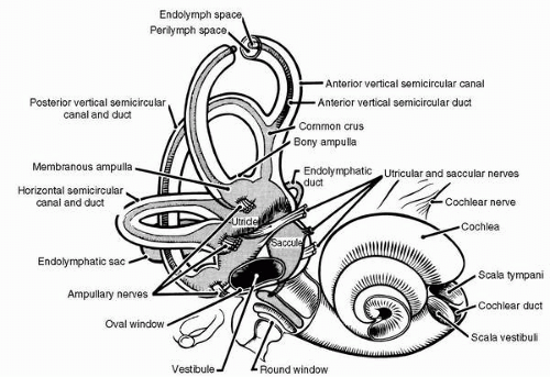 FIGURE 6-3 Gross anatomy of the inner ear. The bony semicircular canals and vestibule contain the membranous semicircular ducts and otolith organs, respectively. |
Vestibular Anatomy
End Organs
The vestibular end organs are smaller than most people realize, measuring just 1.5 cm across and reside in some of the densest bone in the body, the petrous portion of the temporal bone. Each temporal bone contains a tortuous excavation known as the bony labyrinth, which is filled with perilymph, a fluid much like cerebrospinal fluid. The bony labyrinth consists of three main parts: the cochlea, the vestibule, and the semicircular canals (Figure 6-3). Within each part of the bony labyrinth is a part of the delicate, tubular, membranous labyrinth, which contains endolymph, a fluid characterized by its relatively high concentration of positive ions. In the cochlea, the membranous labyrinth is called the cochlea duct or scala media; this organ converts acoustic energy into neural information. In the vestibule lie the two otolith organs, the utricle and the saccule. They translate gravitational and inertial forces into spatial orientation information—specifically, information about the angular position (tilt) and linear motion of the head. They are in effect, linear accelerometers. Semicircular ducts, in the semicircular canals, convert inertial torques into information about angular motion of the head. They function as angular accelerometers. The three semicircular canals and their included semicircular ducts are oriented in three mutually perpendicular planes, thereby inspiring the names of the canals: anterior vertical (or superior), posterior vertical (or posterior), and horizontal (or lateral).
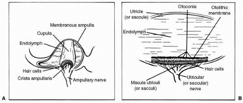 FIGURE 6-4 The vestibular end organs. A: The ampulla of the semicircular duct, containing the crista ampullaris and cupula. B: A representative otolith organ, with its macula and otolithic membrane. |
The semicircular ducts communicate at both ends with the utricle, and one end of each duct is dilated to form an ampulla. Inside each ampulla lies a crest of neuroepithelium, the crista ampullaris. Atop the crista, occluding the duct, is a gelatinous structure called the cupula (Figure 6-4A). The hair cells of the crista ampullaris project their cilia into the base of the cupula. When inertial torques of the endolymph ring, in the semicircular duct, deviate the cupula the cilia are bent.
Lining the bottom of the utricle in a more or less horizontal plane is another patch of neuroepithelium, the macula utriculi, and on the medial wall of the saccule in a vertical plane is still another, the macula sacculi (Figure 6-4B). The cilia of the hair cells comprising these structures project into overlying otolithic membranes, one above each macula. The otolithic membranes are gelatinous structures containing many tiny calcium carbonate crystals, called otoconia, which are held together by a network of connective tissue. Having approximately three times the density of the surrounding endolymph, the otolithic membranes displace endolymph and shift position relative to their respective maculae when subjected to changing gravitoinertial forces. This shifting of the otolithic membrane position results in bending of the cilia of the macular hair cells.
The hair cell is the functional unit of the vestibular sensory system. It converts spatial and temporal patterns of mechanical energy applied to the head into neural information. Each hair cell possesses one relatively large kinocilium on one side of the top of the cell and up to 100 smaller stereocilia on the same surface, except for the area covered by the large kinocilium. Hair cells therefore exhibit morphologic polarization, that is, they are oriented in a particular direction. The functional correlate of this polarization is when the cilia of a hair cell are bent in the direction of its kinocilium, the cell undergoes an electrical depolarization, and the frequency of action potentials generated in the vestibular neuron attached to the hair cell increases above a certain resting frequency; the greater the deviation of the cilia, the higher the frequency. Similarly, when its cilia are bent away from the side with the kinocilium, the hair cell undergoes an electrical hyperpolarization, and the frequency of action potentials in the corresponding neuron in the vestibular nerve decreases (Figure 6-5).
The same basic process described earlier occurs in all of the hair cells in the three cristae and both maculae; the important differences lie in the physical events that cause the deviation of cilia and in the directions in which the
various groups of hair cells are oriented. The hair cells of a crista ampullaris respond to the inertial torque of the ring of endolymph contained in the attached semicircular duct as the reacting endolymph exerts pressure on the cupula causing deviation. The hair cells of a macula, on the other hand, respond to the gravitoinertial force acting to displace the overlying otolithic membrane. As indicated in Figure 6-6A, all of the hair cells in the crista of the horizontal semicircular duct are oriented so that their kinocilia are on the utricular side of the ampulla. Therefore, utriculopetal endolymphatic pressure on the cupula deforms the cilia of these hair cells toward the kinocilia, and all the hair cells in the crista depolarize. The hair cells in the cristae of the vertical semicircular ducts are oriented in the opposite manner, that is, their kinocilia are all on the side away from the utricle. In the ampullae of the vertical semicircular ducts, therefore, utriculopetal endolymphatic pressure deforms the cilia away from the kinocilia, causing all of the hair cells in these cristae to hyperpolarize. In contrast, the hair cells of the maculae are not oriented unidirectionally across the neuroepithelium: the direction of their morphologic polarization depends on where they lie on the macula (Figure 6-6B). In both maculae, there is a central line of reflection, on opposing sides of which the hair cells assume an opposite orientation. In the utricular macula, the kinocilia of the hair cells are all oriented toward the line of reflection, whereas in the saccular macula they are oriented away from it. Because the line of reflection on each macula curves at least 90 degrees, the hair cells, having morphologic polarization roughly perpendicular to this line, assume virtually all possible orientations on the plane of the macula. Therefore, the orthogonality of the planes of the three semicircular ducts enables them to efficiently detect angular motion in any plane, and the perpendicularity of the planes of the maculae plus the omnidirectionality of the orientation of the hair cells in the maculae allow the efficient detection of gravitoinertial forces acting in any direction (12). It remains for the brain to integrate the information gathered by these peripheral sensors.
various groups of hair cells are oriented. The hair cells of a crista ampullaris respond to the inertial torque of the ring of endolymph contained in the attached semicircular duct as the reacting endolymph exerts pressure on the cupula causing deviation. The hair cells of a macula, on the other hand, respond to the gravitoinertial force acting to displace the overlying otolithic membrane. As indicated in Figure 6-6A, all of the hair cells in the crista of the horizontal semicircular duct are oriented so that their kinocilia are on the utricular side of the ampulla. Therefore, utriculopetal endolymphatic pressure on the cupula deforms the cilia of these hair cells toward the kinocilia, and all the hair cells in the crista depolarize. The hair cells in the cristae of the vertical semicircular ducts are oriented in the opposite manner, that is, their kinocilia are all on the side away from the utricle. In the ampullae of the vertical semicircular ducts, therefore, utriculopetal endolymphatic pressure deforms the cilia away from the kinocilia, causing all of the hair cells in these cristae to hyperpolarize. In contrast, the hair cells of the maculae are not oriented unidirectionally across the neuroepithelium: the direction of their morphologic polarization depends on where they lie on the macula (Figure 6-6B). In both maculae, there is a central line of reflection, on opposing sides of which the hair cells assume an opposite orientation. In the utricular macula, the kinocilia of the hair cells are all oriented toward the line of reflection, whereas in the saccular macula they are oriented away from it. Because the line of reflection on each macula curves at least 90 degrees, the hair cells, having morphologic polarization roughly perpendicular to this line, assume virtually all possible orientations on the plane of the macula. Therefore, the orthogonality of the planes of the three semicircular ducts enables them to efficiently detect angular motion in any plane, and the perpendicularity of the planes of the maculae plus the omnidirectionality of the orientation of the hair cells in the maculae allow the efficient detection of gravitoinertial forces acting in any direction (12). It remains for the brain to integrate the information gathered by these peripheral sensors.
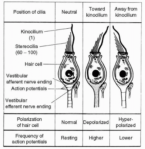 FIGURE 6-5 Function of a vestibular hair cell. When mechanical forces deviate the cilia toward the side of the cell with the kinocilium, the hair cell depolarizes and the frequency of action potentials in the associated afferent vestibular neuron increases. When the cilia are deviated in the opposite direction, the hair cell hyperpolarizes and the frequency of action potentials decreases. |
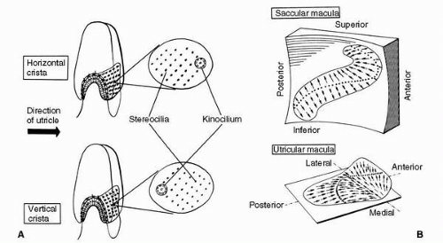 FIGURE 6-6 Morphologic polarization in vestibular neuroepithelia. A: All the hair cells in the cristae of the horizontal semicircular ducts are oriented so that their kinocilia are in the direction of the utricle; those hair cells in the cristae of the vertical ducts have their kinocilia directed away from the utricle. B: The maculae of the saccule (above) and utricle (below) also exhibit polarization—the arrows indicate the direction of the kinocilia of the hair cells in the various regions of the maculae. (Adapted from Spoendlin HH. Ultrastructural studies of the labyrinth in squirrel monkeys. The role of the vestibular organs in the exploration of space. NASA-SP-77. Washington, DC: National Aeronautics and Space Administration, 1965.) |
Neural Pathways
To help the reader better organize the potentially confusing vestibular neuroanatomy, a somewhat simplified overview of the major neural connections of the vestibular system is presented in Figure 6-7. The utricular nerve, two saccular nerves, and the three ampullary nerves converge to form the vestibular nerve, a portion of the VIII cranial vestibulocochlear or acoustic nerve. Within the vestibular nerve lies the vestibular (or Scarpa’s) ganglion, which comprises cell bodies of the vestibular neurons. The dendrites of these bipolar neurons invest the hair cells of the cristae and maculae; most of their axons terminate in the four vestibular nuclei in the brainstem—the superior, medial, lateral, and inferior nuclei—but some axons enter the phylogenetically ancient parts of the cerebellum to terminate in the fastigial nuclei and in the cortex of the flocculonodular lobe and other parts of the posterior vermis.
The vestibular nuclei project through secondary vestibular tracts to the motor nuclei of the cranial and spinal nerves
and to the cerebellum. Because vestibulo-ocular reflexes are a major function of the vestibular system, it is not surprising to find ample projections from the vestibular nuclei to the nuclei of the oculomotor, trochlear, and abducens nerves (cranial nerves III, IV, and VI, respectively). The major pathway of these projections is the ascending medial longitudinal fasciculus (MLF). The basic vestibulo-ocular reflex is therefore served by sensor and effector cells and an intercalated three-neuron reflex arc from the vestibular ganglion to the vestibular nuclei to the nuclei innervating the extraocular muscles. In addition, indirect multisynaptic pathways course from the vestibular nuclei through the paramedian pontine reticular formation to the oculomotor and other nuclei. The principle of ipsilateral facilitation and contralateral inhibition through an interneuron clearly operates in vestibulo-ocular reflexes, and numerous crossed internuclear connections provide evidence of this. The vestibulo-ocular reflexes that the various ascending and crossed pathways support serve to stabilize the retinal image by moving the eyes in the direction opposite to that of the motion of the head. Through the descending MLF and medial vestibulospinal tract, crossed and uncrossed projections from the vestibular nuclei reach the nuclei of the spinal accessory nerve (cranial nerve XI) and motor nuclei in the cervical cord. These projections form the anatomic substrate for vestibulocollic reflexes, which serve to stabilize the head by appropriate action of the sternocleidomastoid and other neck muscles. A third projection is that from primarily the lateral vestibular nucleus into the ventral gray matter throughout the length of the spinal cord. This important pathway is the uncrossed lateral vestibulospinal tract, which enables the vestibulospinal (postural) reflexes to help stabilize the body with respect to an inertial frame of reference by means of sustained and transient vestibular influences on basic spinal reflexes. Secondary vestibulocerebellar fibers course from the vestibular nuclei into the ipsilateral and contralateral fastigial nuclei and to the cerebellar cortex of the flocculonodular lobe and elsewhere. Returning from the fastigial and other cerebellar nuclei, crossed and uncrossed fibers of the cerebellobulbar tract terminate in the vestibular nuclei and in the associated reticular formation. There are also efferent fibers from the cerebellum, probably arising in the cerebellar cortex, which terminate not in nuclear structures but on dendritic endings of primary vestibular afferent neurons in the vestibular neuroepithelia. Such fibers are those of the vestibular efferent system, which appears to modulate or control the information arising from the vestibular end organs. This creates plasticity in the system, allowing for adaptation. This becomes very important in the environment of flight with “excess” acceleration, or in space, with a “deficit” of acceleration. The primary and secondary vestibulocerebellar fibers and those returning from the cerebellum to the vestibular area of the brainstem comprise the juxtarestiform body of the inferior cerebellar peduncle. This structure, along with the vestibular end organs, nuclei, and projection areas in the cerebellum, collectively constitute the so-called vestibulo cerebellar axis, the neural complex responsible for processing primary spatial orientation information and initiating adaptive and protective behavior based on that information and integrating all sources of environmental orientation information.
and to the cerebellum. Because vestibulo-ocular reflexes are a major function of the vestibular system, it is not surprising to find ample projections from the vestibular nuclei to the nuclei of the oculomotor, trochlear, and abducens nerves (cranial nerves III, IV, and VI, respectively). The major pathway of these projections is the ascending medial longitudinal fasciculus (MLF). The basic vestibulo-ocular reflex is therefore served by sensor and effector cells and an intercalated three-neuron reflex arc from the vestibular ganglion to the vestibular nuclei to the nuclei innervating the extraocular muscles. In addition, indirect multisynaptic pathways course from the vestibular nuclei through the paramedian pontine reticular formation to the oculomotor and other nuclei. The principle of ipsilateral facilitation and contralateral inhibition through an interneuron clearly operates in vestibulo-ocular reflexes, and numerous crossed internuclear connections provide evidence of this. The vestibulo-ocular reflexes that the various ascending and crossed pathways support serve to stabilize the retinal image by moving the eyes in the direction opposite to that of the motion of the head. Through the descending MLF and medial vestibulospinal tract, crossed and uncrossed projections from the vestibular nuclei reach the nuclei of the spinal accessory nerve (cranial nerve XI) and motor nuclei in the cervical cord. These projections form the anatomic substrate for vestibulocollic reflexes, which serve to stabilize the head by appropriate action of the sternocleidomastoid and other neck muscles. A third projection is that from primarily the lateral vestibular nucleus into the ventral gray matter throughout the length of the spinal cord. This important pathway is the uncrossed lateral vestibulospinal tract, which enables the vestibulospinal (postural) reflexes to help stabilize the body with respect to an inertial frame of reference by means of sustained and transient vestibular influences on basic spinal reflexes. Secondary vestibulocerebellar fibers course from the vestibular nuclei into the ipsilateral and contralateral fastigial nuclei and to the cerebellar cortex of the flocculonodular lobe and elsewhere. Returning from the fastigial and other cerebellar nuclei, crossed and uncrossed fibers of the cerebellobulbar tract terminate in the vestibular nuclei and in the associated reticular formation. There are also efferent fibers from the cerebellum, probably arising in the cerebellar cortex, which terminate not in nuclear structures but on dendritic endings of primary vestibular afferent neurons in the vestibular neuroepithelia. Such fibers are those of the vestibular efferent system, which appears to modulate or control the information arising from the vestibular end organs. This creates plasticity in the system, allowing for adaptation. This becomes very important in the environment of flight with “excess” acceleration, or in space, with a “deficit” of acceleration. The primary and secondary vestibulocerebellar fibers and those returning from the cerebellum to the vestibular area of the brainstem comprise the juxtarestiform body of the inferior cerebellar peduncle. This structure, along with the vestibular end organs, nuclei, and projection areas in the cerebellum, collectively constitute the so-called vestibulo cerebellar axis, the neural complex responsible for processing primary spatial orientation information and initiating adaptive and protective behavior based on that information and integrating all sources of environmental orientation information.
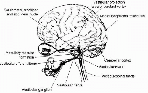 FIGURE 6-7 Major connections and projections of the vestibular system. |
Several additional projections, more obvious functionally than anatomically, are those to certain autonomic nuclei of the brainstem and to the cerebral cortex. The dorsal motor nucleus of cranial nerve X (vagus) and other autonomic cell groups in the medulla and pons receive secondary vestibular fibers, largely from the medial vestibular nucleus; these fibers mediate vestibulovegetative reflexes, which are manifested during motion sickness as pallor, perspiration, nausea, and vomiting that can result from excessive or otherwise abnormal vestibular stimulation. Through vestibulothalamic and thalamocortical pathways, vestibular information eventually reaches the primary vestibular projection area of the cerebral cortex, located in the parietal and parietotemporal cortex. This projection
area is provided with vestibular, visual, and somatosensory proprioceptive representation and is evidently associated with conscious spatial orientation and with integration of sensory correlates of higher-order motor activity. In addition, vestibular information can be transmitted through long polysynaptic pathways through the brainstem reticular formation and medial thalamus to wide areas of the cerebral cortex; the nonspecific cortical responses to vestibular stimuli that are evoked through this pathway appear to be associated with an arousal or alerting mechanism.
area is provided with vestibular, visual, and somatosensory proprioceptive representation and is evidently associated with conscious spatial orientation and with integration of sensory correlates of higher-order motor activity. In addition, vestibular information can be transmitted through long polysynaptic pathways through the brainstem reticular formation and medial thalamus to wide areas of the cerebral cortex; the nonspecific cortical responses to vestibular stimuli that are evoked through this pathway appear to be associated with an arousal or alerting mechanism.
Vestibular Information Processing
While reading the discussion of the anatomy of the vestibular end organs, the reader probably deduced that angular accelerations are adequate physiologic stimuli for the semicircular ducts, and linear accelerations and gravity are adequate stimuli for the otolith organs. This statement, illustrated in Figure 6-8, is the cardinal principle of vestibular mechanics. How the reactive torques and gravitoinertial forces stimulate the hair cells of the cristae and maculae, respectively, and produce changes in the frequency of action potentials in the associated vestibular neurons has already been discussed. The resulting frequency-coded messages are transmitted into the various central vestibular projection areas as raw orientational data to be further processed as necessary for the various functions served by such data. These functions are the vestibular reflexes, voluntary movement, and the perception of orientation.
Vestibular Reflexes
As stated so well by Melvill Jones (13), “…for control of eye movement relative to space the motor outflow can operate on three fairly discrete anatomical platforms, namely: (1) the eye-in-skull platform, driven by the external eye muscles, rotating the eyeball relative to the skull; (2) the skull-on-body platform driven by the neck muscles; and (3) the body platform, operated by the complex neuromuscular mechanisms responsible for postural control.”
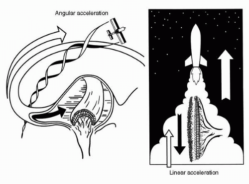 FIGURE 6-8 The cardinal principle of vestibular mechanics: angular accelerations stimulate the semicircular ducts; linear accelerations and gravity stimulate the otolith organ. |
In humans, the retinal image is stabilized mainly by vestibulo-ocular reflexes, primarily those of semicircular-duct origin. A simple demonstration can help one appreciate the contribution of the vestibulo-ocular reflexes to retinalimage stabilization. Holding the extended fingers half a meter or so in front of the face, one can move the fingers slowly from side to side and still see them clearly because of visual (optokinetic) tracking reflexes. As the frequency of movement increases, one eventually reaches a point where the fingers cannot be seen clearly—they are blurred by the movement. This point is approximately 60 degrees/s or 1 or 2 Hz for most people. Now, if the fingers are held still and the head is rotated back and forth at the frequency at which the fingers became blurred when they were moved, the fingers remain perfectly clear. Even at considerably higher frequencies of head movement, the vestibulo-ocular reflexes initiated by the resulting stimulation of the semicircular ducts function to keep the image of the fingers clear. Therefore, at lower frequencies of movement of the external world relative to the body or vice versa, the visual system stabilizes the retinal image by means of optokinetic reflexes. As the frequencies of such relative movement become greater, however, the vestibular system, by means of vestibulo-ocular reflexes, assumes progressively more of this function, and at the higher frequencies of relative motion characteristically generated only by motions of the head and body, the vestibular system is responsible for stabilizing the retinal image.
The mechanism by which stimulation of the semicircular ducts results in retinal image stabilization is simple, at least conceptually (Figure 6-9). When the head is turned to the right in the horizontal (yaw) plane, the angular acceleration of the head creates a reactive torque in the ring of endolymph of the horizontal semicircular duct. The reacting endolymph
then exerts pressure on the cupula, deviating the cupula in the right ear in an utriculopetal direction, depolarizing the hair cells of the associated crista ampullaris and increasing the frequency of the action potentials in the corresponding ampullary nerve. In the left ear, the endolymph deviates the cupula in an utriculofugal direction, thereby hyperpolarizing the hair cells and decreasing the frequency of the action potentials generated. As excitatory neural signals are relayed to the contralateral lateral rectus and ipsilateral medial rectus muscles, and inhibitory signals are simultaneously relayed to the antagonists, a conjugate deviation of the eyes results from the described changes in ampullary neural activity. The direction of the conjugate eye deviation is the same as that of the angular reaction of the endolymph, and the angular velocity of the deviation is proportional to the pressure exerted by the endolymph on the cupula. Therefore, the resulting eye movement is compensatory, adjusting the angular position of the eye to compensate for changes in angular position of the head and thereby preventing slippage of the retinal image over the retina. Because the amount of angular deviation of the eye is physically limited, rapid movements of the eye in the direction opposite to the compensatory motion are employed to return the eye to its initial position or to advance it to a position from which it can sustain a compensatory sweep for a suitable length of time. These rapid eye movements are anticompensatory, and because of their very high angular velocity, motion is not perceived during this phase of the vestibulo-ocular reflex.
then exerts pressure on the cupula, deviating the cupula in the right ear in an utriculopetal direction, depolarizing the hair cells of the associated crista ampullaris and increasing the frequency of the action potentials in the corresponding ampullary nerve. In the left ear, the endolymph deviates the cupula in an utriculofugal direction, thereby hyperpolarizing the hair cells and decreasing the frequency of the action potentials generated. As excitatory neural signals are relayed to the contralateral lateral rectus and ipsilateral medial rectus muscles, and inhibitory signals are simultaneously relayed to the antagonists, a conjugate deviation of the eyes results from the described changes in ampullary neural activity. The direction of the conjugate eye deviation is the same as that of the angular reaction of the endolymph, and the angular velocity of the deviation is proportional to the pressure exerted by the endolymph on the cupula. Therefore, the resulting eye movement is compensatory, adjusting the angular position of the eye to compensate for changes in angular position of the head and thereby preventing slippage of the retinal image over the retina. Because the amount of angular deviation of the eye is physically limited, rapid movements of the eye in the direction opposite to the compensatory motion are employed to return the eye to its initial position or to advance it to a position from which it can sustain a compensatory sweep for a suitable length of time. These rapid eye movements are anticompensatory, and because of their very high angular velocity, motion is not perceived during this phase of the vestibulo-ocular reflex.
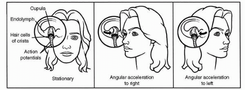 FIGURE 6-9 Mechanism of action of a horizontal semicircular duct and the resulting reflex eye movement. Angular acceleration to the right increases the frequency of action potentials originating in the right ampullary nerve and decreases in those of the left one. This pattern of neural signals causes extraocular muscles to rotate the eyes in the direction opposite to that of head rotation, thereby stabilizing the retinal image with a compensatory eye movement. Angular acceleration to the left has the opposite effect. |
With rapid, high-frequency rotations of the head, the rotational inertia of the endolymph acts to deviate the cupula as the angular velocity of the head builds, and the angular momentum gained by the endolymph during the brief acceleration acts to drive the cupula back to its resting position when the head decelerates to a stop. The cupula-endolymph system thereby functions as an integrating angular accelerometer, that is, it converts angular acceleration data into a neural signal proportional to the angular velocity of the head. This is true for angular accelerations occurring at frequencies normally encountered in terrestrial activities. When angular accelerations outside the dynamic response range of the cupula-endolymph system are experienced, the system no longer provides accurate angular velocity information. When angular accelerations are relatively sustained or when the cupula is kept in a deviated position by other means, such as caloric testing (water 7°C above or below body temperature is instilled into the external auditory canal, adjacent to the horizontal semicircular canal, and thermal convection in the endolymph is generated), the compensatory and anticompensatory phases of the vestibulo-ocular reflex are repeated, resulting in beats of ocular nystagmus (Figure 6-10). The compensatory phase of the vestibulo-ocular reflex is then called the slow phase
of nystagmus, and the anticompensatory phase is called the fast or quick phase. The direction of the quick phase is used to label the direction of the nystagmus because the direction of the rapid motion of the eye is easier to determine clinically. The vertical semicircular ducts operate in an analogous manner, with the vestibulo-ocular reflexes elicited by their stimulation being appropriate to the plane of the angular acceleration resulting in that stimulation. Therefore, a vestibulo-ocular reflex with downward compensatory and upward anticompensatory phases results from the stimulation of the vertical semicircular ducts by pitch-up (−αy) angular acceleration and with sufficient stimulation in this plane, upbeating vertical nystagmus results. Angular accelerations in the roll plane result in vestibulo-ocular reflexes with clockwise and counterclockwise compensatory and anticompensatory phases and in rotary nystagmus. Other planes of stimulation are associated with other directions of eye movement such as oblique or horizontorotary.
of nystagmus, and the anticompensatory phase is called the fast or quick phase. The direction of the quick phase is used to label the direction of the nystagmus because the direction of the rapid motion of the eye is easier to determine clinically. The vertical semicircular ducts operate in an analogous manner, with the vestibulo-ocular reflexes elicited by their stimulation being appropriate to the plane of the angular acceleration resulting in that stimulation. Therefore, a vestibulo-ocular reflex with downward compensatory and upward anticompensatory phases results from the stimulation of the vertical semicircular ducts by pitch-up (−αy) angular acceleration and with sufficient stimulation in this plane, upbeating vertical nystagmus results. Angular accelerations in the roll plane result in vestibulo-ocular reflexes with clockwise and counterclockwise compensatory and anticompensatory phases and in rotary nystagmus. Other planes of stimulation are associated with other directions of eye movement such as oblique or horizontorotary.
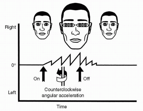 FIGURE 6-10 Ocular nystagmus-repeating compensatory and anticompensatory eye movements resulting from vestibular stimulation. In this case, the stimulation is a yawing angular acceleration to the left, and the anticompensatory, or quick phase, nystagmic response is also to the left. |
As should be expected, there also are vestibulo-ocular reflexes of otolith-organ origin. Initiating these reflexes are the shearing actions that bend the cilia of macular hair cells as inertial forces or gravity cause the otolithic membranes to slide to various positions over their maculae (Figure 6-11). Each position that can be assumed by an otolithic membrane relative to its macula evokes a particular spatial pattern of frequencies of action potentials in the corresponding utricular or saccular nerve, and that pattern is associated with a particular set of compatible stimulus such as backward tilt of the head or forward linear acceleration. These patterns of action potentials from the various otolith organs are correlated and integrated in the vestibular nuclei and cerebellum with orientational information from the semicircular ducts and other sensory modalities; appropriate orientational percepts and motor activities eventually result. Lateral (ay) linear accelerations can elicit horizontal reflexive eye movements, including nystagmus, presumably as a result of utricular stimulation. Similarly, vertical (az) linear accelerations can elicit vertical eye movements, most likely as a result of stimulation of the saccule; the term elevator reflex is sometimes used to describe this response because it is readily provoked by the vertical linear accelerations associated with riding in an elevator. The utility of these horizontal and vertical vestibulo-ocular reflexes of the otolith-organ origin is readily apparent: like the reflexes of semicircular-duct origin, they help stabilize the retinal image. Less obvious is the usefulness of the ocular countertorsion reflex (Figure 6-12), which repositions the eyes about the visual (anteroposterior) axes in response to
otolith-organ stimulation resulting from tilting the head laterally in the opposite direction. Presumably, this reflex contributes to retinal image stabilization by providing a response to changing directions of the force of gravity.
otolith-organ stimulation resulting from tilting the head laterally in the opposite direction. Presumably, this reflex contributes to retinal image stabilization by providing a response to changing directions of the force of gravity.
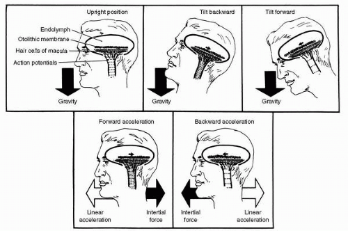 FIGURE 6-11 Mechanism of action of an otolith organ. A change in direction of the force of gravity (above) or a linear acceleration (below) causes the otolithic membrane to shift its position with respect to its macula, thereby generating a new pattern of action potentials in the utricular or saccular nerve. Shifting of the otolithic membranes can elicit compensatory vestibulo-ocular reflexes and nystagmus, as well as perceptual effects. |
 FIGURE 6-12 Ocular countertorsion, a vestibulo-ocular reflex of otolith-organ origin. When the head is tilted to the left, the eyes rotate to the right to assume a new angular position about the visual axes, as shown. |
Our understanding of the vestibulocollic reflexes has not developed to the same degree as that of the vestibuloocular reflexes, although measurements of head rotation in response to vestibular stimulation have been used clinically. Perhaps this situation reflects the fact that vestibulocollic reflexes are not as effective as the vestibulo-ocular reflexes in stabilizing the retinal image, at least not in humans. Such is not the case in other species; birds exhibit extremely effective reflex control of head position under conditions of bodily motion. The high level of development of the vestibulocollic reflexes in birds is either a case or a consequence of the relative immobility of birds’ eyes in their heads. Nonetheless, the ability of a human (or any other vertebrate with a mobile head) to keep the head upright with respect to the direction of applied gravitoinertial force is maintained by means of tonic vestibular influences on the muscles of the neck.
Vestibulospinal reflexes operate to assure stability of the body. Transient linear and angular accelerations, such as those experienced in tripping and falling, provoke rapid activation of various groups of extensor and flexor muscles to return the body to the stable position or at least to minimize the ultimate effect of the instability. Everyone has experienced the reflexive arm movements that serve to break a fall, and most have observed the more highly developed righting reflexes that cats exhibit when dropped from an upside-down position; these are examples of vestibulospinal reflexes. Less spectacular, but nevertheless extremely important, are the sustained vestibular influences on posture that are exerted through tonic activation of so-called antigravity muscles such as hip, knee, and calf extensors. These vestibular reflexes, of course, help keep the body upright with respect to the direction of the force of gravity.
Voluntary Movement
It is known that the various reflexes of vestibular origin serve to stabilize the body in general and the retinal image in particular. The vestibular system is also important in that it provides data for the proper execution of voluntary movement. To realize just how important such vestibular data are in this context, one must first recognize the fact that skilled voluntary movements are ballistic. Once initiated, the movements are executed according to a predetermined pattern and sequence without the benefit of simultaneous sensory feedback to the higher neural levels from which they originate. The simple act of writing one’s signature, for example, involves such rapid changes in speed and direction of movement that conscious sensory feedback and adjustment of motor activity are virtually precluded, at least until the act is nearly completed, at which time the precognitive process becomes recognizable. Learning an element of a skill therefore involves developing a computer-program-like schedule of neural activations that can be called up to effect a particular desired end product of motor activity. Of course, the raw program for a particular voluntary action is not sufficient to permit the execution of that action. Information regarding such parameters as intended magnitude and direction of movement must be furnished from the conscious sphere, and data indicating the position and motion of the body platform relative to the surface of the Earth must be furnished from the preconscious sphere. The necessity for the additional information can be seen in the signature-writing example cited earlier: one can write large or small, quickly or slowly, and on a horizontal or vertical surface. Obviously, different patterns or neuromuscular activation, even grossly different muscle groups, are needed to accomplish a basic act under varying spatial and temporal conditions. The necessary adjustments are made automatically, however, without conscious intervention. Vestibular and other sensory data providing spatial orientation information for use in either skilled voluntary- or reflexive-motor activities are processed into a preconscious orientational percept that provides the informational basis on which such automatic adjustments are made. Therefore one can decide what the outcome of his or her action is to be and initiate the command to do it without consciously having to discern the direction of the force of gravity, analyze its potential effects on planned motor activity, select appropriate muscle groups and modes of activation to compensate for gravity, and then activate and deactivate each muscle in proper sequence and with proper timing to accomplish the desired motor activity. The body takes care of the details, using stored programs for elements of skilled motor activity,
and the current preconscious orientational percept. This whole process is the major function and responsibility of the vestibulocerebellar axis.
and the current preconscious orientational percept. This whole process is the major function and responsibility of the vestibulocerebellar axis.
Conscious Percepts
Usually as a result of the same information processing that provides the preconscious orientational percept, one is also provided a conscious orientational percept. This perception can be false, in which case the individual is said to experience an orientational illusion or to have SD. Moreover, one can be aware that what the body is signaling is not what the mind has concluded from the other orientational information, such as flight instrument data. Conscious orientational percepts can therefore be either natural or derived, depending on the source of the orientation information and the perceptual process involved, and an individual can experience both natural and derived conscious orientational percepts at the same time. Because of this, pilots who have become disoriented in flight commonly exhibit vacillating control inputs, as they alternate indecisively between responding first to one percept and then to the other.
Thresholds of Vestibular Perception
Often, an orientational illusion occurs because the physical event resulting in or from a change in bodily orientation is below the threshold of perception. For example, a person seated in a rotating restaurant perched atop a tower, such as the Seattle Space Needle, cannot sense the rotation of the room. The restaurant completes a 360-degree rotation in 1 hour, therefore its motion is 0.1 degrees/s. The student of disorientation should be aware of the approximate perceptual thresholds associated with the various modes of vestibular stimulation. These thresholds were first described in 1875 by Ernst Mach with considerable accuracy after observing passengers on the great Ferris wheel in Vienna (14). Mach’s observations of relationships of the observer to perception would greatly influence Albert Einstein’s theory of relativity a few years later (15).
The lowest reported threshold for perception of rotation is 0.035 degrees/s2, but this degree of sensitivity is obtained only with virtually continuous angular acceleration and long response latencies (20-40 seconds). Other observations put the perceptual threshold between roughly 0.1 and 2.0 degrees/s2; reasonable values are 0.14, 0.5, and 0.5 degrees/s2 for yaw, roll, and pitch motions, respectively. It is common practice, however, to describe the thresholds of the semicircular ducts in terms of the angular acceleration-time product, or angular velocity, which results in just perceptible rotation. This product, known as Mulder’s constant, remains fairly constant for stimulus times of approximately 5 seconds or less. Using the reasonable value of 2 degrees/s for Mulder’s constant, an angular acceleration of 5 degrees/s2 applied for half a second would be perceived because the acceleration-time product is above the 2-degree/s angular velocity threshold. But a 10-degree/s2 acceleration applied for a 10th of a second would not be perceived because it would be below the angular velocity threshold, nor would a 0.2-degree/s2 acceleration applied for 5 seconds be perceived. In-flight experiments have shown that blindfolded pilot subjects are unable to perceive consistent roll rates of 1.0 degree/s or less, but can perceive a roll when the velocity is 2.0 degrees/s or higher. Pitch rate thresholds in flight are also between 1.0 and 2.0 degrees/s. However, when aircraft pitch motions are coupled with compensatory power adjustments to keep the net G force always directed toward the aircraft floor, the pitch threshold is raised well above 2.0 degrees/s (10).
The perceptual threshold related to otolith-organ function involves both angle and magnitude because the otolith organs respond to linear accelerations and gravitoinertial forces, both of which have direction and intensity. A 1.5-degree change in direction of applied G force is perceptible under ideal (experimental) conditions. The minimum perceptible intensity of linear acceleration has been reported by various authors to be between 0.001 and 0.03 g, depending on the direction of acceleration and the experimental method used. Values of 0.01 g for az and 0.006 g for ax accelerations are appropriate representative thresholds, and a similar value for ay acceleration is probably reasonable. Again, these absolute thresholds apply when acceleration is either sustained or applied at relatively low frequencies. The threshold for linear accelerations applied for less than approximately 5 seconds is a constant acceleration-time product, or linear velocity, of approximately 0.3 to 0.4 m/s.
Unfortunately for those who would like to calculate the exact orientational percepts resulting from a particular set of linear and angular accelerations, like those which might have occurred before an aircraft mishap, the actual vestibular perceptual thresholds may vary significantly (16).
The most common reason for an orientational perceptual threshold to be raised is inattention to orientational cues because attention is directed to something else. Other reasons might be a low state of mental arousal, fatigue, drug effects, or innate individual variation. Therefore, it appears that a given individual can monitor his or her own orientation with considerable sensitivity under some circumstances and with relative insensitivity under others. This inconsistency can lead to perceptual errors that result in orientational illusions.
Components of the vestibular system have characteristic frequency responses and stimulation by patterns of acceleration outside the optimal, or “design,” frequency-response ranges of the semicircular ducts and otolith organs causes the vestibular system to make errors and generate orientational illusions. The existence of absolute vestibular thresholds and the fact that vestibular thresholds are time varying do not influence the generation of orientational illusions. In flight, much of the stimulation resulting from the acceleratory environment is indeed outside of the design frequency-response ranges of the vestibular end organs; consequently, orientational illusions occur in flight. Elucidation of this important point is provided in the section Spatial Disorientation.
Vestibular Suppression and Enhancement
Like all sensory systems, the vestibular system exhibits a decreased response to stimuli that are persistent (adaptation) or repetitious (habituation). Even more important to the aviator is the fact that with time and practice, one can develop the ability to suppress natural vestibular responses, both perceptual and motor. This ability is termed vestibular suppression. Closely related to the concept of vestibular suppression is that of visual dominance, the ability to obtain and use spatial orientation cues from the visual environment despite the presence of potentially strong vestibular cues. Importantly, vestibular suppression seems to be exerted through visual dominance because it disappears in the absence of vision. The opposite effect, an increase in perceptual and motor responsiveness to vestibular stimulation, is termed vestibular enhancement. Such enhancement can occur when the stimulation is novel, as in an amusement park ride or an aircraft spinning out of control. The first time is always the most sensational.
There is some evidence attributing the function of controlling gain of the vestibular system to the efferent vestibular neurons so as to effect suppression and enhancement. The actual mechanisms involved appear to be much more complex than would be necessary to merely provide gross changes in the gain of the vestibular end organs. Precise control of vestibular responses to anticipated stimulation, based on sensory efferent copies of voluntary commands for movement, is probably exercised by the cerebellum through a feed-forward loop involving the vestibular efferent system. Therefore, when discrepancies between anticipated and actual stimulation generate a neural error signal, a response is evoked and vestibular reflexes and heightened perception occur.
Therefore, vestibular suppression involves the development of accurate estimates of vestibular responses to orientational stimuli repeatedly experienced and the active countering of anticipated responses by spatially and temporally patterned sensory efferent activity. Vestibular enhancement, on the other hand, results from the lack of available estimates of vestibular responses because of the novelty of the stimulation, or perhaps from a revision in neural processing strategy obligated by the failure of normal negative feed-forward mechanisms to provide adequate orientation information. Such marvelous complexity of vestibular function assures adaptability to a wide variety of motional environments and thereby promotes survival in them.
OTHER SENSES OF MOTION AND POSITION
Although the visual and vestibular systems play a dominant role in spatial orientation, the contributions of other sensory systems to orientation cannot be overlooked. Especially important are the nonvestibular proprioceptors: the muscle, tendon, and joint receptors and the cutaneous exteroceptors. This is because the orientational percepts derived from the function of these proprioceptors during flight generally support those derived from vestibular information processing, whether accurate or inaccurate. The utility of these other sensory modalities can be appreciated in view of the fact that in the absence of vision our vestibular, muscle, tendon, joint, and skin receptors allow us to maintain spatial orientation and postural equilibrium to a great extent, at least on the Earth’s surface. Similarly, in the absence of vestibular function, vision and the remaining proprioceptors and cutaneous mechanoreceptors are sufficient for appropriate orientation and balance. When two components of this triad of orientational senses are absent or substantially compromised, however, it becomes impossible to maintain sufficient spatial orientation to permit postural stability and effective locomotion, at least until adaptation has occurred.
Nonvestibular Proprioceptors
Sherrington’s “proprioceptive” or “self-sensing” sensory category includes the vestibular (or labyrinthine), muscle, tendon, and joint senses. However, proprioception is generally spoken of as though it means only the nonvestibular components.
Muscle and Tendon Senses
Within skeletal muscle there are complex sensory end organs, called muscle spindles (Figure 6-13A). These end organs are comprised mainly of small intrafusal muscle fibers that lie parallel to the larger extrafusal muscle fibers and are partially enclosed by a fluid-filled bag (17,18).
The sensory innervation of these structures consists mainly of large, rapidly conducting afferent neurons that originate as primary (annulospiral) or secondary (flower-spray) endings on the intrafusal fibers and terminate in the spinal cord on anterior horn cells and interneurons. Stretching of extrafusal muscle results in an increase in the frequency of action potentials in the afferent nerve from the intrafusal fibers; contraction of the muscle results in a decrease or absence of action potentials. The more interesting aspect of muscle spindle function, however, is that the intrafusal muscle fibers are innervated by motoneurons (γ efferents and others) and can be stimulated to contract, thereby altering the afferent information arising from the spindle. Therefore, the sensory input from the muscle spindles can be biased by descending influences from higher neural centers such as the vestibulocerebellar axis.
Although the muscle spindles are structurally and functionally in parallel with associated muscle groups and respond to changes in their length, the Golgi tendon organs (Figure 6-13B) are functionally in series with the muscles and respond to changes in tension. A tendon organ consists of a fusiform bundle of small tendon fascicles with intertwining neural elements, and is located at the musculotendon junctions or wholly within the tendon. Unlike that of the muscle spindle, its innervation is entirely afferent.
The major function of both the muscle spindles and the tendon organs is to provide the sensory basis for myotatic (or muscle stretch) reflexes. These elementary
spinal reflexes operate to stabilize a joint by providing, in response to an increase in length of a muscle and concomitant stimulation of its included spindles, monosynaptic excitation and contraction of the stretched agonist (e.g., extensor) muscle and disynaptic inhibition and relaxation of its antagonist (e.g., flexor) muscle through the action of an inhibitory interneuron. In addition, tension developed on associated tendon organs results in disynaptic inhibition of the agonist muscle, thereby regulating the amount of contraction generated. The myotatic reflex mechanism is the foundation of posture and locomotion. Modification of these and other basic spinal reflexes by organized facilitatory or inhibitory intervention originating at higher neural levels, either through direct action on skeletomotor (α) neurons or through stimulation of fusimotor (primarily γ) neurons to muscle spindles, results in sustained postural equilibrium and other purposive motor behavior. Moreover, some researchers have speculated that when certain types of SD occur during flight this organized modification of spinal reflexes is interrupted as cerebral cortical control of motor activity is replaced by lower brainstem and spinal control. Perhaps the “frozen-on-the-controls” type of disorientation-induced deterioration of flying ability is a reflection of primitive reflexes caused by disorganization of higher neural functions.
spinal reflexes operate to stabilize a joint by providing, in response to an increase in length of a muscle and concomitant stimulation of its included spindles, monosynaptic excitation and contraction of the stretched agonist (e.g., extensor) muscle and disynaptic inhibition and relaxation of its antagonist (e.g., flexor) muscle through the action of an inhibitory interneuron. In addition, tension developed on associated tendon organs results in disynaptic inhibition of the agonist muscle, thereby regulating the amount of contraction generated. The myotatic reflex mechanism is the foundation of posture and locomotion. Modification of these and other basic spinal reflexes by organized facilitatory or inhibitory intervention originating at higher neural levels, either through direct action on skeletomotor (α) neurons or through stimulation of fusimotor (primarily γ) neurons to muscle spindles, results in sustained postural equilibrium and other purposive motor behavior. Moreover, some researchers have speculated that when certain types of SD occur during flight this organized modification of spinal reflexes is interrupted as cerebral cortical control of motor activity is replaced by lower brainstem and spinal control. Perhaps the “frozen-on-the-controls” type of disorientation-induced deterioration of flying ability is a reflection of primitive reflexes caused by disorganization of higher neural functions.
 FIGURE 6-13 Some of the nonvestibular proprioceptive and cutaneous exteroceptive receptors subserving spatial orientation. A: Muscle spindle, with central afferent (sensory) and more peripheral efferent (fusimotor) innervations. B: Golgi tendon organ. C: Lamellated, spray-type, and free-nerve-ending joint receptors. D: Two of the many types of mechanoreceptors found in the skin: lamellated Pacinian corpuscles and spray-type Ruffini corpuscles. |
Despite the obvious importance of the muscle spindles and tendon organs in the control of motor activity, there is little evidence to indicate that their response to orientational stimuli, such as when one stands vertically in a 1-G environment, results in any corresponding conscious proprioceptive percept. Nevertheless, it is known that the dorsal columns and other ascending spinal tracts carry muscle afferent information to medullary and thalamic relay nuclei and then to the cerebral sensory cortex. Furthermore, extensive projections into the cerebellum, through dorsal and ventral spinocerebellar tracts, ensure that proprioceptive information from the afferent terminations of the muscle spindles and tendon organs is integrated with other orientational information and is relayed to the vestibular nuclei, cerebral cortex, and elsewhere as needed.
Joint Sensation
In contrast to the stimulation with the so-called muscle and tendon senses discussed earlier, it has been well established that sensory information from the joints does reach consciousness. In fact, the threshold for perception of joint motion and position can be quite low: as low as 0.5 degree for the knee joint when moved at a rate greater than 1.0 degree/s. The receptors in the joints are of three types
as shown in Figure 6-13C: (a) lamellated or encapsulated Pacinian corpuscle-like end organs, (b) spray-type structures, known as Ruffini-like endings when found in joint capsules and Golgi tendon organs when found in ligaments, and (c) free nerve endings. The Pacinian corpuscle-like terminals are rapidly adapting and are sensitive to quick movement of the joint, whereas both of the spray-type endings are slowly adapting and serve to signal slow joint movement and joint position. There is evidence that polysynaptic spinal reflexes can be elicited by stimulation of joint receptors, but their nature and extent are not well understood. Proprioceptive information from the joint receptors projects through the dorsal funiculi eventually to the cerebral sensory cortex and through the spinocerebellar tracts to the anterior lobe of the cerebellum.
as shown in Figure 6-13C: (a) lamellated or encapsulated Pacinian corpuscle-like end organs, (b) spray-type structures, known as Ruffini-like endings when found in joint capsules and Golgi tendon organs when found in ligaments, and (c) free nerve endings. The Pacinian corpuscle-like terminals are rapidly adapting and are sensitive to quick movement of the joint, whereas both of the spray-type endings are slowly adapting and serve to signal slow joint movement and joint position. There is evidence that polysynaptic spinal reflexes can be elicited by stimulation of joint receptors, but their nature and extent are not well understood. Proprioceptive information from the joint receptors projects through the dorsal funiculi eventually to the cerebral sensory cortex and through the spinocerebellar tracts to the anterior lobe of the cerebellum.
One must not infer from this discussion that only muscles, tendons, and joints have proprioceptive sensory receptors. Both lamellated and spray-type receptors, as well as free nerve endings, are found in fascia, aponeuroses, and other connective tissues of the musculoskeletal system, and they presumably provide proprioceptive information to the central nervous system.
Cutaneous Exteroceptors
The exteroceptors of the skin include mechanoreceptors, which respond to touch and pressure; thermoreceptors, which respond to heat and cold; and nociceptors, which respond to noxious mechanical and/or thermal events and give rise to sensations of pain. Of the cutaneous exteroceptors, only the mechanoreceptors contribute significantly to orientation.
A variety of receptors are involved in cutaneous mechanoreception: spray-type Ruffini corpuscles, lamellated Pacinian and Meissner corpuscles, branched and straight lanceolate terminals, Merkel Cells, and free nerve endings (Figure 6-13D). The response patterns of mechanoreceptors are also numerous: 11 different types of responses, varying from high-frequency transient detection through several modes of velocity detection to more or less static displacement detection, have been recognized. Pacinian corpuscles and certain receptors associated with hair follicles are very rapidly adapting and have the highest mechanical frequency responses responding to sinusoidal skin displacements in the range of 50 to 400 Hz. Therefore, they are well suited to monitor vibration and transient touch stimuli. Ruffini corpuscles are slowly adapting and, therefore, respond primarily to sustained touch and pressure stimuli. Merkel cells appear to have a moderately slowly adapting response making them suitable for monitoring static skin displacement and velocity. Meissner corpuscles seem to primarily detect velocity of skin deformation. Other receptors provide various types of responses to complete the spectrum of mechanical stimuli that can be sensed through the skin. The mechanical threshold for the touch receptors is quite low at less than 0.03 dyne/cm2 on the thumb. In comparison, the labyrinthine receptors subserving audition are 100 times lower at 1-dB sound pressure level representing 0.0002 dyne/cm2.
Related posts:


Stay updated, free articles. Join our Telegram channel

Full access? Get Clinical Tree


