7 Principles of Radiation Physics
In this chapter, we present the basic radiation physics needed for the practice of radiation oncology. Many of the specific applications of these basic physics principles, such as brachytherapy and treatment planning, are presented elsewhere in this textbook. Since the primary audience for this textbook is assumed to be practicing radiation oncologists and resident clinicians, many topics are not treated in the detail that would be required by radiation physicists. Excellent physics textbooks that present the topics in more depth are available.1–4
Basic Concepts
Atomic and Nuclear Structure
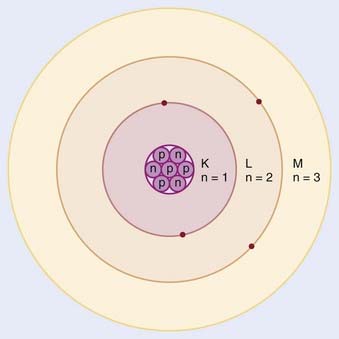
In the planetary model of the atom, first described by Niels Bohr, the electron orbits make up discrete concentric shells, with a different binding energy associated with each shell. The shells are labeled K, L, M, and so on from the innermost to the outermost shell. The maximum number of electrons allowed in each shell is 2n2, where n = 1 for the K shell, n = 2 for the L shell, and so on. Therefore, there are up to 2 electrons in the K shell, 8 in the L shell, 18 in the M shell, and so on. A simple schematic drawing of the Bohr model is shown in Fig. 7-1.
Nuclear Transformations
The explanation of nuclear decay depends on understanding the interplay between the very strong, attractive nuclear force that binds the neutrons and protons together in the nucleus, and the moderately strong repulsive electromagnetic force between the protons. As the protons and neutrons move about within the nucleus, there is some probability that one of them will acquire enough kinetic energy to escape from the nuclear potential energy “well.” Large nuclei with many neutrons and protons tend to be less stable because of the increasing repulsion of the protons. For large nuclei to be stable, an excess of neutrons is required to provide the nuclear attraction to keep the protons from escaping. Fig. 7-2 shows the line of stable nuclei for the range of known elements.
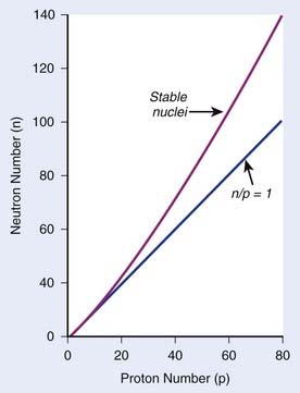
FIGURE 7-2 • Plot of numbers of neutrons and protons in stable nuclei.
(From Khan FM: The physics of radiation therapy, ed 3, Philadelphia, 2003, Lippincott Williams & Wilkins, p 4.)
Decay Constant
where N is the number of radioactive nuclei and λ is the decay constant. The minus sign indicates that the number of nuclei is decreasing with time. Integration of this differential equation leads to the following equation:
where N0 is the number of radioactive nuclei initially present, N(t) represents the number remaining at time t, and e is the base of the natural logarithm (2.71828).
where A0 is the initial activity and A(t) is the activity at time t. The unit of activity is the Curie (Ci) or the Becquerel (Bq), which is 1 disintegration per second:
Half-Life and Mean Life
the mean or average life (Tλ) is the time for the number of atoms to decay to 1/e of the initial number, so
Radioactive Decay Series and Equilibrium
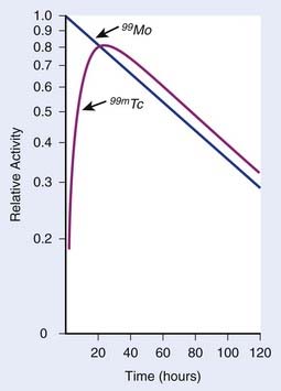
In each series, the half-life of the parent is longer than any of the half-lives of any of the daughter nuclides. This phenomenon leads to a state of transient or secular equilibrium. Since each daughter is less stable than the original parent, the activity of the daughter will increase with time, until it approaches the activity of the long-lived parent. If the half-lives are very different, the activities will become essentially identical after a number of daughter half-lives, and this is called secular equilibrium. An example is shown in Fig. 7-3. If the half-lives of the parent and daughter are very similar, transient equilibrium is reached in a few half-lives, after which the daughter has an activity in excess of the parent activity but decays with the same rate as the limiting parent decay rate. An example of this phenomenon is shown in Fig. 7-4. For either case, after a time that is long compared to the half-life of the shorter-lived nuclide,
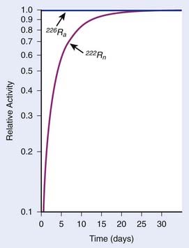
FIGURE 7-3 • Example of secular equilibrium in the decay of 226Ra to 222Rn.
(From Khan FM: The physics of radiation therapy, ed 3, Philadelphia, 2003, Lippincott Williams & Wilkins, p 19.)
where Ai and Ti refer to the activity and half-life of the daughter (d) or parent (p).
X-Ray Production
Characteristic X-Rays
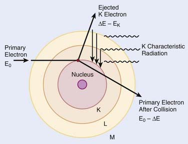
When electrons are incident on target atoms, they can ionize those atoms by depositing sufficient energy to eject an inner shell electron. The inner shell vacancy is subsequently filled by an outer shell electron, causing the emission of a characteristic x-ray with energy equal to the difference between the binding energies of the inner and outer shells. This process is diagrammed in Fig. 7-5. Although this process can take place in both low-Z and high-Z atoms, only for high-Z atoms are the binding energies sufficient to produce radiation in the x-ray portion of the electromagnetic spectrum. For example, the binding energy of K-shell electrons in tungsten, a common target for x-ray tubes and accelerators, is about 70 keV, whereas for aluminum, it is only about 1.5 keV. As mentioned earlier, the characteristic x-ray energy is occasionally transferred directly to an orbital electron, leading to the production of an Auger electron.
Bremsstrahlung X-Rays
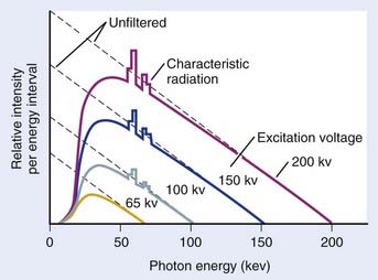
In general, both bremsstrahlung and characteristic x-rays are present when electrons strike a target. Fig. 7-6 shows x-ray spectra for a thick tungsten target for electron energies of from 65 keV to 200 keV. Note the appearance of the characteristic x-rays on top of the bremsstrahlung spectrum once the electron energy is in excess of the K-shell binding energy of 70 keV. Any material in the x-ray beam, including the target itself, will absorb some of the energy of the beam. The effect of such absorption is to preferentially filter out the low energy portion of the bremsstrahlung spectrum. The process of preferentially attenuating the low-energy component of the beam is referred to as “beam hardening.” When the beam is hardened, the average energy of the x-rays increases at the expense of reduced intensity.
Interaction of X-Rays and Particles With Matter
X-Ray Interactions
where dN is the reduction in the number of photons due to interactions in a thickness dx of an absorber, N is the number of incident photons, and µi is the attenuation coefficient for the ith interaction process. After integration over the thickness, this equation becomes
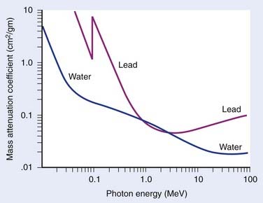
where N(x) is the number of photons left in the beam (without interaction) as a function of the thickness x of material traversed, and µtot is the sum of the individual attenuation coefficients. (µi/ρ) is called the mass-attenuation coefficient for process i, where ρ is the density of the material. Dividing the conventional attenuation coefficients by density removes the dependence on the physical density of materials and the resulting mass attenuation coefficients are approximately equal from material to material. The corresponding thickness, ρx, is in units of grams per square centimeter (g/cm2). The total mass attenuation coefficients for water and lead are shown as functions of energy in Fig. 7-7. There are five different photon interaction processes, including coherent scattering, photoelectric effect, Compton scattering, pair production, and photodisintegration. These will be discussed in turn.
implying that
Compton Scattering
Compton scattering is a process in which the incident photon interacts with an orbital electron as if it were a free particle, since the binding energy is small compared to the photon energy. The dynamics of the interaction can be described as a typical particle–particle scattering interaction whereby the photon transfers some of its energy to the electron and is scattered at an angle φ relative to the incident direction. The electron is ejected at an angle θ relative to the forward direction. The energy of the outgoing Compton-scattered photon is equal to the difference between the incident photon energy and the energy transferred to the electron. A diagram of the Compton process is shown in Fig. 7-8.
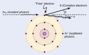
FIGURE 7-8 • Illustration of the Compton effect.
(From Khan FM: The physics of radiation therapy, ed 3, Philadelphia, Lippincott Williams & Wilkins, p 67.)
From conservation of momentum:
and
where ve is the velocity of the electron, me is the rest mass of the electron, c is the speed of light, and
Solving these three simultaneous equations, we obtain the following relationships:
where α = hνo/ mec2 and f = (1 − cos φ).
Relative Importance of Interaction Types
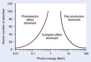
The total mass absorption coefficient is the sum of the coefficients for coherent, photoelectric, Compton, and pair production. For low-Z targets such as tissue (average Z = 7), Compton processes are overwhelmingly dominant throughout the range of energies used in therapy. Fig. 7-9 shows the relative importance of photoelectric, Compton, and pair production as a function of photon energy and the atomic number of the target material.4 For tissue, Compton dominates between approximately 30 keV and 30 MeV, whereas for lead, photoelectric dominates up to approximately 800 keV and pair production above about 5 MeV. Because of its calcium content, bone has a higher absorption by photoelectric and pair production. This leads to high bone doses for orthovoltage and kilovoltage and for higher energy accelerator beams.
Charged Particles
Electrons
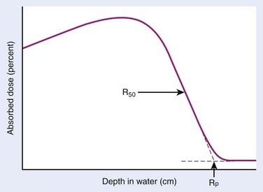
Electrons lose energy to the medium by two processes, ionization and radiation. Ionization processes are interactions with the atomic electrons, whereas radiation losses are interactions with the field of the nucleus, leading to bremsstrahlung x-ray production. Whereas the microscopic interactions are well understood, the macroscopic description of the energy and range of the particles at any point in the medium is not simple. This is because the electrons are very much lighter than the atomic nuclei. Therefore, the electron can lose a very large fraction of its energy in a single process and can be deflected by very large angles. This means that even if the electron beam is monoenergetic when entering a medium, there will be a large amount of range-straggling, or a large variation from electron to electron as to where, in the phantom, the electron will stop. Fig. 7-10 shows a plot of absorbed dose as a function of depth for monoenergetic electrons incident on water. There is a depth beyond which the dose is almost zero, where all the incident electrons have been stopped and where the remaining dose is due to bremsstrahlung x-rays produced by the electrons in the medium. This is in sharp contrast to the exponential falloff of dose for x-rays. This ranging out of electrons in matter is responsible for the popularity of electrons for treatment of superficial disease.
Protons and Heavier Ions
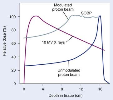
The use of protons and heavy ions for radiotherapy was pioneered in the 1970s and 1980s at the Massachusetts General Hospital in collaboration with the now decommissioned Harvard Cyclotron Laboratory and at the Lawrence Berkeley National Laboratory in Berkeley, California.5–15 Since then, several proton and charged-particle facilities have been built around the world, a list of which can be found on the website for the Particle Therapy Co-Operative Group (PTCOG; http://ptcog.web.psi.ch/). Similar to electrons, protons lose energy primarily by electromagnetic interactions with the atomic electrons. A major difference between protons and electrons is that protons are much heavier than electrons and therefore lose only a very small fraction of their energy in an individual interaction, scattering minimally in the process. Protons lose energy at an increasing rate as they slow down, yielding an enhanced region of energy deposition called the Bragg Peak just before they stop. One can predict very accurately the depth at which the protons will come to rest if the initial energy of the protons and the electron density of the material traversed are known. The absence of exit dose beyond the intended target makes protons nearly ideally suited for optimal physical dose delivery. A typical depth dose distribution for a clinical, energy-modulated proton beam, compared to that of a 10-MV bremsstrahlung x-ray beam, is shown in Fig. 7-11. A small percentage of proton interactions is via nuclear interactions with the nucleus. These rare interactions are qualitatively different than electromagnetic interactions and are thought to be responsible for enhancing the cell kill per unit dose by about 10% to 20% over that of x-rays.16
Heavy ions such as helium, carbon, neon, and argon nuclei have also been used in radiotherapy.9–12,14,15,17,18 Similar to protons, they lose energy by interacting with the atomic electrons. Being even heavier than protons, they scatter even less and have even more rapid dose falloff outside the central beam and even faster falloff of dose beyond the end of range. In addition to these electromagnetic interactions, heavy ions have a probability of interacting with the nucleus via nuclear interactions that increases with the mass of the incident ion. In particular, as the heavy ions begin to slow down, they tend to suffer nuclear interactions in which they lose a very large amount of their energy in a single event. This high density of deposited energy kills cells in a far more efficient way per unit dose than x-rays. These particles are said to have a high radiobiologic efficiency (RBE). For more information on these particles, the reader is referred to the literature.13
Neutrons
Neutrons have also been used in clinical treatments.19–24 These particles are neutral, so they cannot lose energy by any means other than the nuclear interaction. All of their interactions are “catastrophic,” because a significant portion of their energy is deposited in an individual event. Their primary interactions are with protons within the nucleus. These nuclear events result in recoil protons and charged nuclear fragments that have rather low energy and deposit large amounts of energy very close to the site of the original interaction. The falloff of neutron dose with depth is exponential and similar to that of low-energy x-rays, with the depth of the 50% dose being around 10 cm for typical treatment energies. Neutrons are very efficient in producing cell kill per unit dose (high RBE) relative to x-rays for both tumor tissue and normal tissues. Clinical trials have been conducted to investigate the areas where neutrons might have an advantage over x-rays. A summary of the physical characteristics and results of early clinical results is available.13
In addition, clinical trials are under way to investigate the use of slow neutrons, either thermal or epithermal in energy, to treat boronated tumor cells in patients.25–32 The clinical efficacy of these neutrons for cancer therapy depends on the very high cross section for neutron capture by boron and on a high ratio of boron in the tumor cells to that in the surrounding normal cells. To date, clinical results of these trials have been disappointing.
Radiation Therapy Treatment Machines
Kilovoltage Units
A schematic diagram of an x-ray tube suitable for radiation therapy is shown in Fig. 7-12. Since a high-voltage supply is used to generate the accelerating potential for the electron beams, a maximum energy of approximately 300 kV is achievable with this design. The resulting x-ray beams have a spectrum of photon energies with a maximum equal to the energy of the electron beam.

FIGURE 7-12 • Schematic diagram of an x-ray tube that could be used for radiation therapy.
(From Khan FM. The physics of radiation therapy, ed 3, Philadelphia, Lippincott Williams & Wilkins, p 29.)
Megavoltage Units
X-ray and γ-ray beams of energy greater than 1 MV are classified as megavoltage beams. In the 1930s a number of transformer-based and van de Graaff generator–based units working in the 800 KeV to 2 MeV range were installed around the world. However, it was not until the introduction of the 60Co teletherapy machine and the linear accelerator that the routine use of megavoltage x-ray and γ-ray beams occurred, significantly changing the practice of radiotherapy and leading to substantial improvements in clinical results.33
Teletherapy Machines
The megavoltage era began with the introduction of the 60Co teletherapy machine into radiotherapy clinics beginning in 1951.34,35 The development of nuclear reactors in the late 1940s made possible the production of small 60Co sources with specific activities (in Curies per gram) high enough to produce clinically acceptable dose rates of more than 1 Gray (Gy) per minute at a typical treatment distance of 80 cm from the source. These machines quickly became the standard of radiotherapy because of their simplicity of design and operation, low cost, and availability. The two photons produced by the decay of 60Co have energies of 1.17 and 1.33 MeV, yielding a depth-dose curve that falls to 50% of maximum in about 10 cm of water or tissue. In addition, the relatively high energy of the photons leads to “skin sparing” due to a reduced entrance dose that builds up for a distance of 5 mm (the maximum range of the secondary electrons from 60Co photons) to a maximum value. The half-life of 60Co is 5.27 years, making the source change a relatively infrequent requirement. With the highest specific activities currently achievable, dose rates of at least 1.5 Gy per minute for a field size of 40 cm × 40 cm can be achieved at 80 cm source-to-treatment distance.
Betatrons
The next chronological development in treatment machines is the betatron, first developed by D. W. Kerst at the University of Illinois36 primarily for physics experimentation. Electrons with energies of up to 45 MeV have been produced in betatrons for radiotherapy and used either directly or to produce bremsstrahlung x-ray beams. The massive size of these machines, their high cost, and relatively low dose rate combined to limit their usefulness in radiation therapy.
Linear Accelerators
The use of microwaves to accelerate electrons to high energies for radiotherapy was first demonstrated in Great Britain in 1953.37 This became possible primarily because of the development of high-power microwave generators for military radar use during World War II. The major components of a typical medical linear accelerator (linac) are shown in a block diagram in Fig. 7-13. The acceleration of the electron beam takes place in the accelerator wave guide, consisting of a stack of cylindrical cavities with a hole through the center, into which resonant electromagnetic waves of frequency in the microwave range (∼3000 MHz) have been coupled. The electron beam is created and preaccelerated to approximately 50 keV in a conventional electrostatic electron gun, injected into the resonating waveguide, spatially bunched and accelerated through interactions with the electromagnetic field in the individual cavities, and then emerges from the accelerating structure as a narrow pencil beam that can be magnetically bent or focused onto a scattering foil (for electron treatments) or a bremsstrahlung target (for x-ray treatments) in the treatment head of the linac. For low energies of 6 MeV or less, the beam can be magnetically focused in the forward (vertical) direction onto the axis of the treatment head, whereas at higher energies, the beam is usually bent through a 90-degree or 270-degree angle before entering the treatment head since the accelerating structure is much longer for high energies and is frequently oriented horizontally to save space. For more details about the acceleration process, the reader is referred to several excellent review articles in the literature.38–40
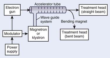
FIGURE 7-13 • A block diagram of a typical medical linear accelerator.
(From Khan FM: The physics of radiation therapy, ed 3, Philadelphia, 2003, Lippincott Williams & Wilkins, p 43.)
Although the details of the acceleration process can be quite technical, the shaping of the beam in the treatment head is both important and conceptually easy to understand. Fig. 7-14
Stay updated, free articles. Join our Telegram channel

Full access? Get Clinical Tree


 . Isotopes of an element have the same Z but different A and, therefore, have the same chemical properties but can have different physical properties. Isobars are atoms with the same A but different Z, and isotones are atoms with different A and Z but the same N.