5
PHOTON TREATMENT
5.2 FACTORS AFFECTING PHOTON DOSE DEPOSITION
5.1 BEAM QUALITY
Explain the concept of “beam quality.” What is one simple way of defining “beam quality”?
Question 2
Explain the concept of “beam hardening.” After a beam passes through a filter, how do the maximum energy, average energy, half-value layer (HVL), and dose rate change?
Question 3
Explain the relationship of tube voltage, tube current, and filament current to the relative output of a kV diagnostic X-ray tube.
Beam quality describes the energy spectrum of an X-ray (or Gamma-ray) photon beam. Some photon beams, for example, Co-60, are nearly monoenergetic [1.25 megaelectron volt (MeV) average]. Other beams, for example, a 6 MV linac beam, are poly-energetic. MeV implies one energy whereas the 6 MV implies a spectrum, with 6 MeV as the maximum energy. The beam quality from each manufacturer and machine is slightly different for beams with the same nominal energy. For therapy photon beams, the detailed beam quality is measured by a curve called the percent depth dose (PDD) curve. The PDD value at 10 cm depth is often used to report the quality of the beam in one number. For diagnostic beams, the kVp or half-value layer is used to define the beam quality instead of PDD.
Answer 2
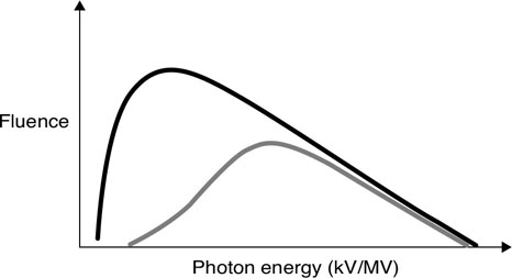
Beam hardening occurs when the beam passes through any matter, which acts as a filter, absorbing low-energy photons. The transmitted beam will have an increased average energy, decreased dose rate while the maximum energy is unchanged. For a diagnostic beam, this increase in energy results in an increase in HVL. In the figure, the black spectrum is the initial beam and the gray is the filtered beam.

Answer 3
The output in a kV X-ray tube is proportional to the tube current, the square of the tube voltage, and exponentially with the filament current.
Question 5
How many half-value layers (HVLs) of the Cerrobend are necessary to limit the transmission to 10% and 1%?
Question 6
How does a physical wedge affect beam quality?
Question 7
Does a virtual wedge affect the beam quality?
Cerrobend is an alloy of bismuth, lead, tin, and cadmium. It is useful as a high density (9.4 g/cm3) and high-Z material with a low melting point to quickly create a block in a desired shape. The goal is to achieve ≤5% primary beam transmission which means 4.3 half value layers of cerrobend or more.
Answer 5
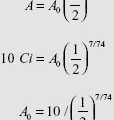
3.322 HVLs are necessary to limit the dose to 10% transmission. 6.644 HVLs are necessary for 1% transmission. As you can see, 3.3222 ![]() is a useful number to remember to quickly calculate exponential decay as applied to either radioactive decay or transmission through HVLs.
is a useful number to remember to quickly calculate exponential decay as applied to either radioactive decay or transmission through HVLs.
Answer 6
A physical wedge, comprised of a triangle-shaped metal material that generates a gradient of beam intensities at depth. This differentially filters the low-energy X-rays, leading to beam hardening. The degree of beam hardening is more pronounced near the thicker “heel” of the wedge. A physical wedge is also responsible for increased scatter.
Answer 7
A virtual wedge does not produce variable beam hardening as the gradient profile is created by slowly opening one collimator jaw of the linear accelerator, rather than transmission through a physical wedge. Any scatter from the jaw is reduced by shielding in the head of the machine and does not contribute significantly to the dose experienced by the patient.
Describe the spatial distribution of photons generated by bremsstrahlung. How is the distribution affected by the energy of the incident electron?
Question 9
What is a Thoraeus filter?
Question 10
Why is the order of layers in the Thoraeus filter important?
Question 11
What are bremsstrahlung interactions and why do they happen?
For kV incident electron energies, the X-rays are produced isotropically (in all directions). With megavolt (MV) incident electron energies, the X-ray distribution becomes progressively more aligned with the direction of the incident electrons. Therefore, a kV X-ray tube may use a reflection target where useful X-rays are at 90° to the electron beam, whereas an MV linear accelerator uses a transmission target.
Answer 9
A Thoraeus filter is commonly used with diagnostic X-ray tubes. The filter consists of tin, copper, and aluminum layers to remove low-energy photons and characteristic X-rays from the beam. These low-energy photons do not contribute to image quality but increase patient dose.
Answer 10
The order of filter layers is important because tin contributes the most to filtration of the characteristic X-rays of the tungsten target, which fall between 58 and 69 keV. Tin’s characteristic X-rays are of very low energy and can be filtered with copper. Copper’s characteristic X-rays are filtered by a thin film of aluminum, leading to a hard beam capable of producing sharp images.
Answer 11
Bremsstrahlung interactions occur when a high-energy electron pass near the nucleus of an atom. The electron is deflected by the nucleus due to its Coulomb force. The electron undergoes sudden acceleration in a different direction, losing all or part of its energy in the process, which is converted into a photon. A single electron may undergo multiple bremsstrahlung interactions before finally coming to rest.
Question 13
Describe the source of and difference between inherent and added filtration.
Question 14
How is beam penumbra defined?
Question 15
What are the three main sources of beam penumbra in therapy photon beams?
High-energy photon beams are created by bremsstrahlung interactions and therefore contain a spectrum of energies. The most probable energy is approximately one third that of the maximum energy, which by convention is used to name the beam. Therefore, for a 10 MV beam the maximum energy is 10 MeV and the most probable energy is approximately 3.33 MeV. This is not the same as the average energy, which is more difficult to calculate.
Answer 13
Inherent filtration in a linear accelerator is typically caused by the tungsten target itself—as electrons interact with the target, a spectrum of photons are created via bremsstrahlung interactions. The low-energy photons may interact and be absorbed by the remaining tungsten before emerging as a part of the spectrum. This effect increases as the thickness of the target increases. Added filtration is intentionally placed in the path of a beam with the goal of increasing the average beam energy (beam hardening) or decreasing the intensity of a beam.
Answer 14
Beam penumbra (umbra is Latin for “shadow”) is the gradual reduction of beam intensity at the edge of a photon field. It is typically measured as the width between the 80% and 20% isodose lines, although 90% to 10% isodose lines are also used.
Answer 15
The three main sources of beam penumbra are transmission penumbra, geometric penumbra, and internal penumbra. Transmission penumbra occurs as the beam passes through the edge of the jaw, block, or multileaf collimator (MLC). Geometric penumbra occurs because the source is not a point-source. Internal penumbra is due to scatter within the patient.
Is there a difference between the first and second half-value layer (HVL) for a cobalt unit? What about a diagnostic X-ray tube?
Question 17
How is the beam energy changed by the flattening filter?
Question 18
How is the beam flatness specified?
Cobalt-60 generates a near-monoenergetic beam (1.17 MeV, 1.32 MeV combined for an average of 1.25 MeV) and therefore the HVL1 = HVL2 = HVL3. However, diagnostic tubes use bremsstrahlung X-ray generation to produce a spectrum of energies. After the beam passes through the first HVL, due to the concept of “beam hardening,” the second HVL is now greater than the first.
Answer 17
X-ray intensity is forward peaked after the target before the flattening filter. The flattening filter is thicker in the middle and tapers off toward the edges so that the central region is attenuated more than the periphery to make the beam flat. As a result, the beam will be hardened more in the center than the periphery (lower average energy in the periphery). This results in a beam that is peaked at depths greater than 10 cm. The flattening filter also reduces the dose rate significantly.
Answer 18
Beam flatness is specified at 10 cm depth and within the area bounded by 80% of the field size or 1 cm inside the field edge. The beam flatness should be within +–3% of the central axis dose at 10 cm depth.
Question 20
Parallel opposed beams are frequently used in radiation therapy. They provide uniform dose distribution for the target with a simple and reproducible setup. One disadvantage of this technique is called “tissue lateral effect.” How does this effect change with energy and patient thickness?
Question 21
How is “integral dose” defined and how does it change with energy?
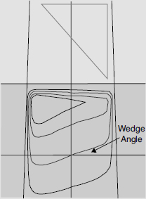
The wedge tilts the isodose lines toward its thin edge. The angle between central axis and the isodose lines at 10 cm depth is the wedge angle.

Answer 20
The midpoint between the opposed beams is the prescription point. The maximum dose to the midpoint dose (prescription point) ratio increases with patient thickness and decreases with energy. As a result, it is better to use higher energy X-ray beams (>10 MV) for large patients (>20 cm) to improve homogeneity of the dose distribution and preserve subcutaneous tissue.
Answer 21
Integral dose is simply mass × dose if dose is uniform throughout the region, or the sum of the energy deposited. If dose volume histogram is calculated, the integral dose is the area under the contour of the external, which includes all tissue of the patient. The unit of “integral dose” is kg/Gy or joule. It is used in determining treatment plan quality in regards to how much dose is delivered outside the target. The integral dose decreases with energy.
What are the advantages and disadvantages of a flattening filter free (FFF) linear accelerator?
Question 23
Define the term “effective energy” for a heterogeneous X-ray beam.
Question 24
What term is used to specify the quality of a megavoltage X-ray beam?
Question 25
Why are electron energies written as megaelectron volts (MeVs) but photon energies as megavolts (MVs)?
New linear accelerators (linacs) are available with an FFF design. Linacs require a flattening filter to produce flat beams across large open fields. However, the flattening filter lowers the dose rate of the machine and produces beam hardening. With small-field intensity modulated radiation therapy (IMRT) treatments, the multileaf collimators (MLCs) are used to deliberately modulate the intensity of the beam. For these treatments, the filter is no longer required. The advantages of this approach include a significantly increased dose rate (>1,000 MU/min versus 300 to 600 MU/min) and decreased variation in energy spectrum (due to beam hardening). The disadvantages of this approach include a possible increase in skin dose (less beam hardening) and the inability to treat large, flat, open fields without the use of the MLCs. Some manufactures add a thin filter to remove very low-energy photons for nonflat beams.
Answer 23
The “effective energy” is defined as the energy of a monoenergetic X-ray beam that has the same half-value layer as the heterogeneous X-ray beam.
Answer 24
The percent depth dose (PDD) value at 10 cm depth of a 10 cm × 10 cm field size with source to skin distance of 100 cm is used to define the beam quality.
Answer 25
Electron energies are monoenergetic as they leave the accelerating waveguide but photons are heterogeneous in energy. MV photon energy represents the highest energy X-ray (in MeVs) in the spectrum.
5.2 FACTORS AFFECTING PHOTON DOSE DEPOSITION
What is the definition of percent depth dose (PDD) for a given field size?
Question 2
How and why is the percent depth dose (PDD) at 10 cm affected by increases in field size, energy, source to skin distance (SSD), and physical wedges?
Question 3
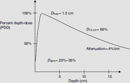
Explain the shape of a megavoltage central-axis percent depth dose (PDD) curve. Graph the PDD curve of a 6 MV beam. Label the curve at 0, 1.5, and 10 cm depth. Label the approximate slope of the beam between 1.5 and 10 cm?
For a given field size, PDD (expressed in percentage) is measured along the central axis and defined as the ratio of a dose at a given depth d to the dose at a reference depth (usually dmax) on the central axis.
![]()
Answer 2
| PDD | Why? | |
|---|---|---|
| Field size | Increases | Increased scatter |
| Energy | Increases | Increased penetration due to increased energy |
| SSD | Increases | Inverse square law (Mayneord factor) |
| Physical wedge | Increases | Beam hardening |
Answer 3
The PDD curve reports dose deposition as a function of depth for a radiation beam. The PDD on the surface for megavoltage energies is below 100% as the incident photons produce high-energy electrons which travel a distance before coming to rest and depositing energy. This effect explains the “skin sparing” properties of megavoltage therapy. The peak in the curve known as Dmax, occurs deeper. The curve then declines, or attenuates, due to a combination of the inverse-square law, absorption, and scatter.

What is the typical dmax for cobalt-60 (Co-60), 6, 10, 15, and 18 MV beams using a 10 cm × 10 cm field size?
Question 5
What is the percent change in the percent depth dose (PDD) per centimeter for cobalt-60 (Co-60), 6 and 10 MV photons under standard conditions?
Question 6
While you are on-call over the weekend you wish to treat a 20 cm long by 8 cm wide posterior to anterior (PA) spine field. Calculate the equivalent square necessary to complete the hand calculation. Why is the equivalent square necessary?
The dmax is slightly different for every machine and beam; however, typical values are 0.5, 1.5, 2.5, 3.0, and 3.2 to 3.5 cm for each energy, respectively.
Answer 5
Co-60 attenuates at approximately 4% per cm, 6 MV beams attenuate at approximately 3.5% per cm, and 10 MV attenuates at approximately 3.3% per cm. Note that these numbers are approximation, as the values change with depth.
Answer 6
![]()
where S is side of equivalent square, A and P are, respectively, the area and perimeter of the rectangular field.

The square field with 11.4 cm side is equivalent to a 20 cm × 8 cm rectangular field. Usually percent depth dose (PDD) or tissue maximum ratio (TMR) values are only tabulated for square fields. A rectangular field will have approximately the same PDD or TMR as its equivalent square field. There are also other more complex methods to approximate the PDD or TMR for irregular field shapes like Clarkson’s method.
Stay updated, free articles. Join our Telegram channel

Full access? Get Clinical Tree


