Patient Positioning and Immobilization
Lawrence E. Reinstein
Matthew B. Podgorsak
Introduction
The primary goal of radiotherapy is the delivery of a prescribed radiation dose to a predefined target volume, either to inactivate a tumor or to treat a benign condition that responds to radiation therapy. A frequently conflicting goal is the avoidance of damage to the patient’s healthy radiosensitive tissues and organs that may be adjacent to the target volume or are in the path of a radiation beam as it is aimed toward the target volume. For many treatments requiring very high doses of radiation, the determining factor in how well we can achieve both goals is the extent to which we can deliver treatment accurately every day for the entire course of radiotherapy. Inadequate dose to all or part of the target volume may lead to treatment failure and possibly death. On the other hand, excessive dose to all or part of an adjacent organ may cause drastic and intolerable complications such as paraplegia, blindness, kidney failure, and so on, that would result in unacceptable post-treatment quality of life for the patient.
Radiation treatment accuracy can be divided into two separate but highly interrelated concepts: dosimetric accuracy and geometric accuracy. This chapter deals only with the latter. It covers issues related to patient positioning and immobilization that have a strong effect on how well we can accurately cover a specified anatomic volume with a desired radiation dose. It does not deal with issues such as radiation beam calibration and dose calculations but only with patient positioning from the time the target volume and critical organ volumes are defined through the daily treatment setup.
Patient Setup for Radiotherapy
Nearly all modern radiotherapy is delivered using a medical linear accelerator. Current medical accelerators provide photon beams in the megavoltage range, typically with a peak energy of 6 MV or greater, and often with dual photon beams and an assortment of electron beams. The photon beam may be controlled by thick tungsten collimators that define a variable field size. These motorized collimators, which can be symmetrical, asymmetrical, or multileaf, are mounted in the head of a gantry that rotates a full 360 degree about an isocenter whose position in space is stable to within 1 mm. A beam central axis can be defined as the straight line between the accelerator target (x-ray source) and the center of the radiation field defined by the symmetrical collimators. If the accelerator geometry is properly aligned, the central axis passes through the isocenter for all gantry angles, forming a vertical plane. Also, it must continue to pass through the isocenter even when the field-defining collimators are rotated about the central axis. Typical specifications on geometric precision for medical accelerators require that for all possible beam orientations, the central axis must pass through a sphere at the isocenter with a radius of 1 mm (1,2). The newest accelerators equipped with onboard imaging capability through cone-beam computed tomography (CT) reconstruction have even tighter geometrical tolerances (isocenter sphere radius of 0.5 mm) to ensure accurate image reconstruction. The accelerator comes with a light field projecting an optical crosshair that precisely indicates the location of the beam central axis during setup.
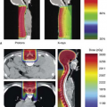
As described above, in general, the goal of radiotherapy is to deliver a high dose to the target volume, at the same time keeping the dose to the surrounding tissues and organs to a minimum, or at least within tolerable levels. Once these structures are identified with a variety of different imaging techniques, a treatment plan is created. Usually, the treatment plan necessitates centering the target volume on the isocenter and firing beams of different apertures from several different gantry and/or couch angles toward the target (Fig. 5.1A).
How can we place the patient so as to ensure that the target is at the isocenter? If we make the simplifying but somewhat unrealistic assumption that the patient is a rigid solid with a flat posterior surface, and therefore the tumor volume and all surrounding organs are frozen, treatment setup is straightforward and well defined. If the patient is supine on a flat, perfectly horizontal treatment couch, a single point (a fiducial mark, often a tattoo or permanent ink) placed on the anterior skin is sufficient to locate the center of the target volume that prior imaging has shown to be at a certain depth, d, beneath the surface. With the gantry angle vertical and central axis pointing downward, the treatment couch can be adjusted in the left-to-right and head-to-toe dimensions until the optical crosshair intersects at this skin mark. Because the accelerator includes a simple tool to indicate the target-to-surface distance (TSD)
and because the target-to-axis (isocenter) distance (TAD) is fixed (at 100 cm for nearly all therapy accelerators), the treatment couch height is simply adjusted until the TSD indicator, a calibrated front pointer, or optical distance indicator (ODI), shows TSD = TAD – d (i.e., TSD = 100 cm—target depth). This positions the target center at the accelerator isocenter.
and because the target-to-axis (isocenter) distance (TAD) is fixed (at 100 cm for nearly all therapy accelerators), the treatment couch height is simply adjusted until the TSD indicator, a calibrated front pointer, or optical distance indicator (ODI), shows TSD = TAD – d (i.e., TSD = 100 cm—target depth). This positions the target center at the accelerator isocenter.
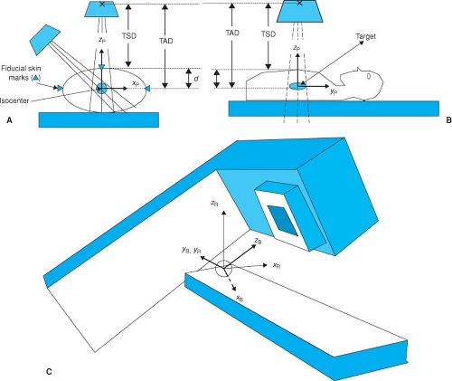 Figure 5.1. A: Cross section of patient illustrating the use of two isocentric beams to encompass the target. The fiducial skin marks are used to set up the patient so that the target is at the isocenter at a depth d. The target-to-skin distance (TSD) and target-to-axis distance (TAD) satisfy the relationship TSD = TAD – d. B: The treatment setup parameters and patient coordinate system shown in the sagittal view. C: Room coordinate and beam coordinate systems as described in text. |
Modern medical accelerators come equipped with a precision motorized and often computer-controllable treatment couch, also known as the patient support assembly. The movements of the treatment couch are carefully specified so that its translational axes are vertical and horizontal. In addition, the couch rotates about a vertical axis passing through the isocenter to allow for nonaxial (noncoplanar) beams for more complex treatment delivery. The setup procedure just described may not be sufficiently well defined even for our fictitious rigid patient. Simply superimposing the target center on the accelerator isocenter allows the possibility that the rigid patient is twisted or rotated, and although the target center would still be treated correctly, the full target volume and the surrounding organs might not be treated as planned. By way of analogy, knowing the x, y, z center-of-mass coordinates of an airplane on its landing approach does not adequately describe the situation: The pilot also must know its roll (lateral tilt), pitch (longitudinal tilt), and yaw (rotation on vertical axis) to land safely. If the posterior surface of the rigid patient is a flat plane, the treatment couch eliminates any ambiguities with respect to roll and pitch of the patient. The problem of yaw, however, remains. An improved and somewhat more complex approach to patient setup enabling fine-tuning of rigid patient rotation has been recently developed. The system
(HexaPOD evo RT System, Elekta Inc., Norcross, GA) includes a robotic treatment couch top that incorporates 6 degrees of freedom in its movement (three translations and three rotations) and can be used to fine-tune patient rotation as well as the center of mass of the target to ensure accurate orientation of the full target volume relative to the treatment beam.
(HexaPOD evo RT System, Elekta Inc., Norcross, GA) includes a robotic treatment couch top that incorporates 6 degrees of freedom in its movement (three translations and three rotations) and can be used to fine-tune patient rotation as well as the center of mass of the target to ensure accurate orientation of the full target volume relative to the treatment beam.
Modern radiotherapy simulator, virtual simulator, and accelerator rooms are equipped with at least three lasers. Two of these are mounted on the sidewalls to the patient’s left and right and are aligned to be horizontal, to pass through the machine isocenter, and to be perpendicular to the isocenter axis. (When these conditions are met, the laser beams are colinear as well.) The third laser is mounted on the ceiling and points straight down through the isocenter. With the patient lying on the couch in the simulator room, the CT room, or any other room similarly equipped, a patient coordinate system can be established, and the points where the laser beams intersect the skin surface can be permanently marked. Although it is typical and convenient to try to place the origin of the patient coordinate system at the target volume center and to align the patient so that his or her longitudinal body axis is parallel to the isocenter axis, it is not altogether necessary. Consistent planning and treatment can be based upon an initial patient origin that is near the target center or even somewhat arbitrary. Optimum choice for the patient coordinate system setup origin is often dictated by the location of the associated fiducial skin marks.
The rigid-solid setup procedure consists of establishing an appropriate patient coordinate system on the radiotherapy simulator couch, carefully creating fiducial point surface marks, and then rotating and translating the patient on the accelerator treatment couch so as to achieve congruence between the patient and room coordinate systems. Congruence is demonstrated when the orthogonal lasers in the accelerator treatment room precisely impinge on the three surface fiducials, two side and one top. Other tools to help verify the alignment include the ODI, which, if the treatment setup is perfect, should indicate the correct central axis depth to the target center (d = TAD – TSD), and the sagittal laser, which is mounted on the wall opposite to the accelerator gantry to provide a longitudinal line parallel to and defining a vertical plane with the horizontal isocenter axis.
For implementation of more complex isocentric treatment plans, it is useful to establish three coordinate systems: the patient coordinate system, the room coordinate system, and the beam coordinate system. The patient coordinate system, already described, is usually defined during therapy simulation, CT imaging for therapy planning, or virtual simulation. During this process the patient should be placed in a comfortable and reproducible position that will become the treatment position. Typically, in this position the patient is lying flat and level, either supine or prone, on the horizontal table without any obvious bending or twisting. The patient’s longitudinal symmetry axis is aligned to the horizontal to become the yp axis of the patient coordinate system. A transverse plane orthogonal to the yp axis contains the zp (pointing straight upward) and xp (pointing horizontally to the supine patient’s left) coordinate axes (Fig. 5.1B). Treatment planning is often simplified if the origin of the patient coordinate system is placed at the center of the treatment target, but this is not always convenient nor is it absolutely necessary. The patient coordinate system should be more or less permanently delineated through the use of fiducial marks on the patient’s skin. It may be advantageous to shift the origin of the patient coordinate system away from the target center to obtain fiducial marks where the skin is taut and relatively immovable and to avoid regions of soft and flabby tissues.
The room coordinate system can be defined with its origin at the isocenter of the medical accelerator. The isocenter plane is defined by the sweep of the beam central axis as the accelerator gantry rotates about the isocenter. The yr axis is defined as orthogonal to this plane passing through the isocenter, the positive direction being toward the gantry support. The xr and zr axes of the room coordinate system are contained in the isocenter plane with positive zr in the vertical (up) direction and positive zr in the horizontal (supine patient’s left) direction (Fig. 5.1C).
The beam coordinate system is defined by the central ray of the radiation beam (zb) and the xb and yb axes, which are in a plane orthogonal to the central ray and pointing perpendicularly toward the field-defining (symmetrical or asymmetrical) collimators. Note that the origin of the beam coordinate system is also at the isocenter and that the beam coordinate system rotates with respect to the room coordinate system with either accelerator gantry or collimator rotation.
The process of patient treatment setup according to an isocentric radiotherapy treatment plan includes the following steps:
The patient is placed on the couch (patient support assembly) in the proper treatment position, supine or prone, with or without wedges, pillows, and immobilization devices.
Properly shifting the patient on the treatment couch and raising the couch to the appropriate height (zr dimension) brings the patient coordinate system into alignment with the room coordinate system, as is verified by precise superpositioning of the orthogonal room lasers with the fiducial skin marks.
With the gantry pointing straight down, secondary confirmation checks are made of the TSD using the ODI such that TSD = TAD – d, where d is the depth to the isocenter. This becomes the proper initial treatment setup position.
The treatment plan is implemented for each field by proper rotation of the gantry and collimator as well as by choice of field size and beam modifiers. This transforms the beam coordinate system with respect to the room coordinate system and hence, because they are
aligned by the initial setup procedure, to the patient coordinate system as well. Before treatment, a secondary check of TSD should also be made for each field.
More complex planning (e.g., noncoplanar, nonaxial, and multiple isocenters) may require further transformation of the patient coordinate system with respect to the room coordinate system and hence with respect to the beam coordinate system. This is achieved by appropriate translation and/or rotation of the treatment couch.
Although the three-point triangulation method is sufficient to prevent the orientation ambiguities (roll, pitch, and yaw) that characterize the single-point method, what about the actual patient, who is far from rigid and who consists of muscle, fat, bone, and so on? It is tempting to suggest that the three-point triangulation method at least ensures that the treatment setup is accurate in the transverse plane defined by this triangle. But even this may not be true. In a perfectly accurate setup the treatment fields would correspond exactly to the planned fields with respect to the target volume and the surrounding tissues and organs. This can be true only if the interrelationship between these anatomic structures with the surface fiducials remains constant in time, both on the imaging or radiotherapy simulator couch and on the treatment couch. Strictly speaking, this is unlikely to be true for any patient.
As we move away from the central triangulation plane in the cephalad or caudad direction, additional differences may arise between the patient localization data (the CT scan, magnetic resonance imaging (MRI), single photon emission computed tomography (SPECT), positron emission tomography (PET) images, or even external surface contours) and the anatomy of the patient lying on the accelerator couch on the day of treatment. While the patient is lying on a hard flat couch, the arm and leg positions can shift, the spine and the neck can flex differently each time, soft tissues and fat can deform under the force of surface contact or of gravity, muscles can contract or relax, and so on. Depending on the location of the treatment site, we cannot be certain that the patient will lie down on the couch each day in the same way as during the localization procedure. Because organ position can change with respect to the patient coordinate system, this can lead to different areas of target undertreatment and critical organ overtreatment each day, with actual delivered dose-volume histograms (DVH) different from the planned DVH.
Depending on the level of accuracy demanded by a particular treatment protocol, aligning the patient with three triangulation points may not be sufficient. Serious errors can occur, particularly when long (in the cephalocaudal dimension) fields are used. A number of steps can reduce the error associated with the soft and flexible nature of the patient. In general, they all attempt to create a comfortable, relaxed, and stable treatment position for the patient, one that can be reasonably well reproduced each day. The more like a rigid body one can make the patient, the more likely it is that correct setup will be accomplished.
Some straightforward suggestions to improve setup accuracy:
Determine a comfortable and relaxed position for the patient. If the position is not comfortable, the patient tends to fidget or move until a more comfortable position is found. Also, if muscles are tense during localization, they may relax as the treatments progress. The use of standard indexed foam wedges, head cups, and Timos can often help.
Make use of the modern laser crosshair system that has replaced the older laser dot system. If properly installed and aligned, the sidewall lasers project lines in precisely vertical and horizontal directions, with the intersection of the crosshairs projecting horizontally through the isocenter. The ceiling laser cross-projects lines straight downward in the transverse and sagittal planes, both intersecting the isocenter. It is important to note that the crosshair intersection point for perfectly installed lasers is projected colinearly to each axis of the room coordinate system. Often, similar systems of laser crosses exist in the simulator or imaging rooms, consequently more extensive markings can be made where these lines intersect the patient’s surface while in the treatment position. These markings can be used as additional setup guides to help return the patient to the same position each day and to avoid errors that result from the natural twisting and flexing of the body. New developments in technology include HeNe lasers that project a green light providing enhanced contrast on skin tones that are problematic with the traditional red laser. Furthermore, green laser projections are sharper on the patient skin due to reduced light scatter in the fine capillaries beneath the skin surface.
Extend the surface markings as far superior and inferior to the central treatment plane as is practical. Rotation of the legs can affect the position of organs within the pelvis. The arms and shoulders can similarly affect the internal anatomy within the thorax. Extending the alignment marks above and below the central plane and even the treatment volume, as discussed in the preceding text, improves reproducibility of target and critical organ placement.
Refer to external anatomic landmarks. Additional reassurance in setting up a patient in a reproducible position can be obtained by measuring and recording the distances between several visible anatomic landmarks or between these landmarks and the laser alignment system. For example, proper head tilt can be tested each day by measuring the distance between the bottom of the chin and the suprasternal notch.
Make use of immobilization devices. There is a detailed discussion of these devices later in this chapter. Many of the newer devices and materials are based upon modern packaging techniques with which fragile electronic equipment or soft produce is protected by hardened foams and thermoplastics that conform to their external
surface. In this way, the soft and flexible item becomes a rigid body. Such devices when customized to radiation oncology patients provide comfort, confinement, and stability that assist in achieving an accurate setup. If the customized device is created during patient localization, the appropriate fiducial marks can be permanently applied to its hard outer surface and hopefully establish a more stable patient coordinate system for use during each treatment setup.
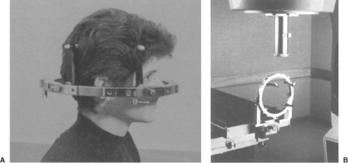
Figure 5.2. A: The BRW/CRW (Brown-Roberts-Wells/Cosman-Roberts-Wells) head ring assembly for stereotactic radiosurgery. B: Head ring assembly attached to the treatment couch for accelerator-based radiosurgery. (Courtesy of Integra, Burlington, MA.)
Although the surface fiducial three-point triangulation system is commonly used for conventional treatments, there are several specialized systems in use today or under development. One, in particular, is the localization and setup used for stereotactic radiosurgery (3,4,5). This single-fraction technique uses small-diameter circular fields for the treatment of arteriovascular malformations (AVMs), acoustic neuromas, brain metastases, primary brain tumors, and recently, functional disorders, for which demands for precision may be greater than in any other external beam treatment (<1 mm overall geometric uncertainty). The variety of commercial systems available include a stereotactic head ring such as is used by neurosurgeons for stereotactic biopsy fixed to the patient’s skull with head posts and skull screws set into the bone. This is an invasive (although relatively simple and painless) procedure, and the frame remains affixed to the patient’s head throughout the localization and treatment (Figs. 5.2A and B).
Specialized localizing devices and fiducial systems attach to the head frame, and allow the positions of the target and critical structures to be determined with a high degree of accuracy within the coordinate system defined by the stereotactic frame. Localizing devices are available for use with CT scan, angiography, and MRI. As with conventional radiotherapy, the planning process includes digitizing the target center and the relevant anatomic structures, once the stereotactic transformation has been determined. For treatment, the head frame can be docked with a base frame mounted either to the treatment couch or the floor. Because the base frames are mechanically aligned to the room coordinate system, it becomes a simple matter to apply a series of spatial translations so that the target is exactly at the isocenter and the head oriented according to the treatment plan. A specialized radiotherapy and neurosurgery tool, known as the Gamma Knife (Elekta Inc., Norcross, GA), has also been successfully applied for intracranial radiosurgery treatments.
One of the reasons stereotactic radiosurgery is so accurate is that there are virtually no changes in the positions of the internal anatomy with respect to the bony skull, either during treatment or day to day. Although it is tempting to try to apply this technique to fractionated radiotherapy, there is one major drawback: It is impractical to have the head frame bolted to the patient’s skull for an entire course of radiotherapy. To address this objection, several relocatable head frames, invasive and noninvasive, have been developed. These are discussed later in this chapter. Furthermore, several systems for body radiosurgery have also been developed and are based on similar principles to traditional intracranial radiosurgery.
An alternative or supplement to treatment setup using surface fiducial marks is radiographic setup and alignment. This approach has been characterized as image-guided radiation therapy (IGRT), and the state of the art in IGRT technology is covered in detail in Chapter 14. A simple example of IGRT is the daily use of portal images before treatment is delivered. To maintain patient flow in a busy clinic, such interventional techniques are practical only if automatic or semiautomatic software tools are available to rapidly compare the portal image taken with an electronic
portal imaging device (EPID) with the digitally reconstructed radiograph (DRR) previously generated for the radiation field in question. For this method, the DRR, which is based upon CT localization data, should contain the outline of the field aperture designed in the treatment planning process as well as contours of visible anatomic structures. Such software tools have been developed and are readily available from numerous manufacturers (e.g., Visicoil Guided Radiotherapy, IBA-Advanced Radiotherapy, Tyngsboro, MA). Several studies using interventional setup techniques show reasonable success (6,7).
portal imaging device (EPID) with the digitally reconstructed radiograph (DRR) previously generated for the radiation field in question. For this method, the DRR, which is based upon CT localization data, should contain the outline of the field aperture designed in the treatment planning process as well as contours of visible anatomic structures. Such software tools have been developed and are readily available from numerous manufacturers (e.g., Visicoil Guided Radiotherapy, IBA-Advanced Radiotherapy, Tyngsboro, MA). Several studies using interventional setup techniques show reasonable success (6,7).
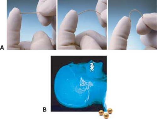 Figure 5.3. A: Three implantable radiopaque markers. (Courtesy of CIVCO and IBA-Advanced Radiotherapy, Tyngsboro, MA.) B: Radiograph showing implanted fiducial marker in the skull. |
Radiographic alignment of patient anatomy using bony landmarks should be more accurate than surface fiducial methods. Studies of daily radiographic alignment of supine patients treated for intracranial targets (8,9) yield positioning accuracy of 1 mm or better. Reasons for the inaccuracy of surface fiducial methods include the inherent limitations of laser and optical alignment devices (discussed later in this chapter) and the instability of internal organs with respect to the skin surface. However, radiographic alignment has its limitations as well. It is not always possible to find the same point on the bony landmark in the two orthogonal views needed to ensure complete three-dimensional (3D) spatial verification. Also, because this method is based upon imaging and repositioning of the bony landmarks within the treatment volume, it makes the underlying assumption that the soft tissue organs are fixed with respect to the skeleton. The reliability of this assumption is highly dependent on the anatomic location and the organs in question, and further study is clearly needed.
The following two forms of radiographic setup do not make this important assumption:
Localization and alignment using radiopaque markers implanted in the target
Setup using daily pretreatment acquisition of patient 3D anatomic information
Implanting radiopaque markers in the target (10,11) make it possible to use, for example, an EPID device to achieve computer-assisted orthogonal localization of the soft tissue target. Several manufacturers currently market implantable fiducial markers (e.g., ACCULOC IGRT fiducial markers [CIVCO], Visicoil [IBA-Advanced Radiotherapy, Tyngsboro, MA]) that are radiographically visible and can be used in conjunction with IGRT techniques for patient setup. Imaging of these radiopaque markers can be done using portal images acquired before treatment delivery. The position of the markers relative to the isocenter is then compared to their position on a DRR obtained from the planning CT scan, and appropriate patient position adjustments can subsequently be made. Figure 5.3A shows two types of implantable fiducial markers and Figure 5.3B shows a radiograph of implanted bone fiducial markers.
Taking this process one step further, the ExacTrac X-ray 6D system (BrainLAB USA, Chicago, IL) is comprised of a pair of kV x-ray tubes recessed into the treatment room floor and aimed at a corresponding pair of amorphous silicon flat panel detectors. These imaging systems, shown in Figure 5.4, provide real-time stereoscopic information regarding the position of bony anatomy or implanted fiducial markers relative to the treatment isocenter. A comparison is then made to the corresponding marker positions on DRRs reconstructed from the planning CT scan, and patient position is robotically modified during treatment to realign the anatomy or markers to their planned positions relative to the isocenter using a treatment couch with 6 degrees of freedom (ExacTrac Robotic Couch, BrainLAB, Chicago, IL).
A different concept in patient setup and positioning involves implanting tiny beacon transponders, consisting of small coils encapsulated in a glass enclosure, within a target volume (Calypso 4D Localization System, Calypso Medical,
Seattle, WA). Rather than using radiographic information to localize these markers, an array, shown in Figure 5.5, placed over the patient activates the transponders through a radiofrequency signal and then listens for the signals that are returned from each transponder. The 3D position of each transponder is determined and compared to the baseline geometry, giving shift coordinates that, once implemented, return the implanted transponders, and, presumably, the target volume, to their planned positions relative to isocenter. Multi-institutional clinical trials have shown that this technology can be efficiently applied to improve the accuracy of prostate localization during external beam radiotherapy (12,13,14). Recently published phantom and animal studies have also documented the potential use of this technology in the treatment of other anatomies (15,16).
Seattle, WA). Rather than using radiographic information to localize these markers, an array, shown in Figure 5.5, placed over the patient activates the transponders through a radiofrequency signal and then listens for the signals that are returned from each transponder. The 3D position of each transponder is determined and compared to the baseline geometry, giving shift coordinates that, once implemented, return the implanted transponders, and, presumably, the target volume, to their planned positions relative to isocenter. Multi-institutional clinical trials have shown that this technology can be efficiently applied to improve the accuracy of prostate localization during external beam radiotherapy (12,13,14). Recently published phantom and animal studies have also documented the potential use of this technology in the treatment of other anatomies (15,16).
 Figure 5.4. ExacTrac X-ray 6D system comprised of a pair of kV x-ray tubes recessed into the treatment room floor and aimed at a corresponding pair of flat panel detectors. (Courtesy of BrainLAB, Chicago, IL.) |
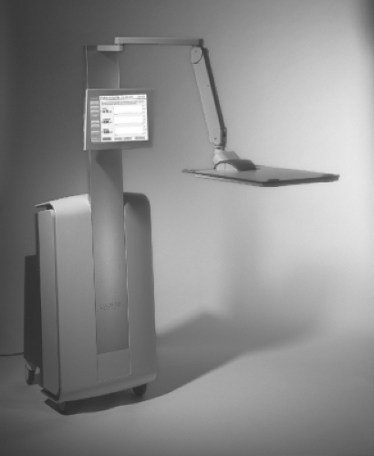 Figure 5.5. Array placed over a patient that activates implanted transponders through a radiofrequency signal and then listens for the signals returned from each transponder. (Courtesy of Calypso Medical, Seattle, WA.) |
The idea of using daily pretreatment CT scans to assist in patient setup on a daily basis may have seemed far-fetched just a few years ago, but several variations of this scheme have been recently developed. The simplest technique is the placement of a commercial diagnostic CT scanner within the medical accelerator room (e.g., Primatom [Siemens Medical Solutions, Malvern, PA]). This paradigm includes a medical accelerator coupled with a standard CT scanner mounted on rails that can be positioned around a patient already setup in treatment position on the linac treatment couch. Once imaging of the target volume is complete and the patient has been appropriately shifted, the CT scanner is moved away so that treatment can be delivered. Of course, this approach requires fast and reliable software to determine what translations and rotations of the patient (patient coordinate system) must be made to best duplicate the dose distribution seen on the approved treatment plan.
A more sophisticated approach involves obtaining tomographic imaging information using the treatment unit itself. One such concept, coined tomotherapy (17) and described in detail elsewhere in this textbook, consists of an X-band accelerating waveguide (linac) mounted on a CT gantry. This beam line can be programmed with the appropriate parameters to obtain either a fan beam CT scan or to deliver a treatment. Patient positioning is fine-tuned before treatment based on the CT scan information, therefore in principle making it possible to duplicate on a daily basis the alignment of the planning target volume (PTV) to the isocenter that was captured at the time of planning CT scan. A different approach, covered in detail in Chapter 14, involves the use of cone-beam CT images obtained with an imaging device that is attached to a standard linear accelerator. Two manufacturers (Varian Medical Systems, Palo Alto, CA and Elekta Inc., Norcross, GA) currently have commercial products that are based on this paradigm. Tomographic information is obtained using a complementary beam line oriented perpendicularly to the treatment beam and comprised of a kV x-ray tube coupled with a digital image detector. A third manufacturer (Siemens Medical Solutions, Malvern, PA) has developed a system using the existing treatment beam to produce 3D target imaging with the patient on the treatment table. All three IGRT systems allow an image set to be reconstructed immediately prior to the delivery of each fraction from projections obtained as the system makes a full rotation around the patient. Similar to the tomotherapy concept, patient positioning can be fine-tuned by comparing the treatment CT scan obtained with the patient on the treatment table to the planning CT scan.
Ultrasound-based systems are also used for patient alignment. Although these systems have found their most common applications in patient positioning for pelvic (primarily prostate) radiotherapy, the positioning of any anatomy that lends itself to ultrasound imaging could, in principle, be verified with an ultrasound-based system. The use of these systems (BATCAM [Best Nomos, Pittsburgh, PA], Clarity [Elekta AB, Stockholm], and SonArray [Varian Medical Systems, Palo Alto, CA]) does not appear to significantly affect patient throughput.
All these radiographic setup techniques are interventional and require a means for the interactive correction of patient position, based on the radiographic information. Usually, this can be achieved through motorized couch movements that have recently incorporated motion in six dimensions (three standard translations plus roll, pitch, and yaw). A clinical system that eliminates the need for patient realignment after setup incorporates a miniature accelerator supported by a robotic arm that can accurately point in almost any direction (CyberKnife Robotic Radiosurgery System, Accuray, Sunnyvale, CA). After the patient is securely supported on a conventional treatment couch, stereo radiographs of the patient are taken with two
ceiling-mounted x-ray tubes and corresponding amorphous silicon flat panel detectors recessed into the floor. These radiographs are compared with the library of DRRs generated during the planning study. The accelerator position and angle can then be adjusted to compensate for variations between the current and planned anatomic positions. This process is repeated during treatment delivery, and fine adjustments to the accelerator positioning are made to correct for patient motion during treatment.
ceiling-mounted x-ray tubes and corresponding amorphous silicon flat panel detectors recessed into the floor. These radiographs are compared with the library of DRRs generated during the planning study. The accelerator position and angle can then be adjusted to compensate for variations between the current and planned anatomic positions. This process is repeated during treatment delivery, and fine adjustments to the accelerator positioning are made to correct for patient motion during treatment.
Patient Setup During Delivery of Radiotherapy
Verification of patient setup and interfraction confirmation of PTV alignment with treatment isocenter have been covered in the preceding text. Some PTVs, particularly those in the thorax and upper abdominal areas, have the potential for intrafraction motion, that is, the PTV can move during the delivery of a fraction of radiotherapy. Technologies that account for this motion have been developed (e.g., RPM Respiratory Gating System [Varian Medical Systems, Palo Alto, CA], Active Breathing Coordinator [Elekta Inc., Norcross, GA], ExacTrac Adaptive Gating [BrainLAB USA, Westchester, IL], Anzai Respiratory Gating Hardware [Siemens Medical Solutions, Malvern, PA]). Most of these systems track the position of a surrogate marker, either externally positioned or implanted within the target volume, and rely on reproducible correlation between the positions of the surrogate and the PTV. Delivery using this type of system has been termed gated radiation therapy because treatment is delivered through a “gate” defined by surrogate position. At least one manufacturer (Accuray, Sunnyvale, CA) has developed a treatment system (CyberKnife Robotic Radiosurgery System with Synchrony Respiratory Tracking System) that can continuously track patient, and, presumably PTV, position during treatment delivery, thereby obviating the need for gating techniques. One group has studied the accuracy of a dynamic MLC-defined field moving in synchrony with a PTV that is itself moving due to respiratory motion (18). These approaches have the potential to be superior to gated delivery because they are more efficient and do not rely on a surrogate marker as the position of the PTV itself can be continuously verified.
Table 5.1 Field Alignment Discrepancy | |||||||||||||||||||||||||||
|---|---|---|---|---|---|---|---|---|---|---|---|---|---|---|---|---|---|---|---|---|---|---|---|---|---|---|---|
| |||||||||||||||||||||||||||
Accuracy and Reproducibility
Numerous studies demonstrate (to no one’s surprise) geometric uncertainties in the delivery of radiotherapy. Whether these go by the name of patient setup errors, field placement errors (FPEs), field aperture errors, or patient position errors, they generally amount to underirradiating part of the intended target, overirradiating normal critical organs, or both. Byhardt et al. (19) found in a study of 337 patient portal films that setup errors >5 mm occurred in 15% of the setups, and for 10% the error was at least 10 mm. Other studies (20,21) estimate the frequency of setup errors >10 mm to be on the order of 20% across all sites when surface fiducial triangulation methods are used without immobilization devices. Also, a portal film study of mantle fields on nonimmobilized patients with Hodgkin’s disease (22) showed block placement errors >10 mm in at least 21% of the patients. Much of the early literature is summarized in a paper by Boyer (23), in which he presents the FPEs as determined by portal film studies of different treatment sites (Table 5.1).
How are we to interpret these studies? What are the causes of these discrepancies? Should they be considered acceptable? Can anything be done to improve the situation? Do these FPEs have a negative clinical effect, and has this been demonstrated?
To answer the last question first, we turn to a theoretical study by Goitein and Buss (24), who found that clinically realistic random setup errors could cause a 12% decrease in tumor control for supraglottic lesions. A clinical study
by Maruyama and Khan (25) reports a 33% recurrence rate in sites adjacent to the blocked areas in patients treated for Hodgkin’s disease with mediastinal involvement, implying that marginal misses have a strong effect on outcome. A more recent report by Kinzie et al. (26), based on Patterns of Care data for 155 patients treated for Hodgkin’s disease at several institutions, found that the local recurrence rate increased from 7% for patients with adequate tumor margins to 33% for those with inadequate ones. Similarly, in a retrospective study of 40 patients by Doss (27) head-and-neck recurrences were found to be correlated with blocking errors, defined as 5 mm or greater with respect to the first approved portal film. Only 7% of the patients with correct fields had recurrent disease versus 75% (p = 0.03) in those with blocking errors. Another retrospective study of 178 patients treated at a single institution for nasopharyngeal carcinoma showed that patients with adequate coverage of the defined target volume had 20% better local control than those with inadequately covered targets.
by Maruyama and Khan (25) reports a 33% recurrence rate in sites adjacent to the blocked areas in patients treated for Hodgkin’s disease with mediastinal involvement, implying that marginal misses have a strong effect on outcome. A more recent report by Kinzie et al. (26), based on Patterns of Care data for 155 patients treated for Hodgkin’s disease at several institutions, found that the local recurrence rate increased from 7% for patients with adequate tumor margins to 33% for those with inadequate ones. Similarly, in a retrospective study of 40 patients by Doss (27) head-and-neck recurrences were found to be correlated with blocking errors, defined as 5 mm or greater with respect to the first approved portal film. Only 7% of the patients with correct fields had recurrent disease versus 75% (p = 0.03) in those with blocking errors. Another retrospective study of 178 patients treated at a single institution for nasopharyngeal carcinoma showed that patients with adequate coverage of the defined target volume had 20% better local control than those with inadequately covered targets.
Taken as a whole, these and other data suggest what is more or less self-evident: Accurate reproducible treatment of the entire target volume with appropriate margins is important for achievement of the best possible results for the patient with cancer. To understand the individual sources of error that lead to the overall uncertainties, we must more clearly define the parameters involved. Fortunately, this has been made easier by the publication of ICRU Report 50: Prescribing, recording and reporting photon beam therapy (28), and the companion publication ICRU Report 62: Prescribing, recording and reporting photon beam therapy (Supplement to ICRU Report 50) (29). The ICRU defines a gross tumor volume (GTV) as “gross palpable or visible/demonstrable extent and location of malignant growth.” The clinical target volume (CTV) includes the GTV “and/or subclinical microscopic malignant disease which have to be eliminated.” It is the CTV that we hope to sterilize or eradicate by the application of radiotherapy.
Related posts:


Stay updated, free articles. Join our Telegram channel

Full access? Get Clinical Tree


