Low-Dose-Rate Brachytherapy
Glenn P. Glasgow
Brachytherapy still prospers! The prior (2nd edition) chapter focused on historical and basic concepts and developments between 1997 and 2005. This revision, best viewed as a supplement to the prior (2nd edition) chapter, deletes some topics, now covered in Chapter 8 (Treatment Planning Algorithms: Brachytherapy), deletes certain historical topics, but adds information published since 2006. Space limitations exclude inclusion of intravascular, liquid I-125 sources, microspheres, nanoparticles, and electronic brachytherapy.
Significant developments include three journal anniversary papers (1,2,3), a task group report on dose prescriptions for prostate permanent seed implants (4), American Association of Physicists in Medicine (AAPM) and European Society for Therapeutic Radiology and Oncology (ESTRO) recommendations for clinical use of sources with energies higher than 50 keV (5), a Supplement TG-43U1S1 (6) to Task Group 43 (TG-43) absorbed dose formalism (7,8), numerous dosimetry reports on existing and new designs of 125I (9,10,11,12) and 103Pd sources (13), and use of photon spectrometry to determine dose-rate constants (14) and numerous dosimetry reports (15,16,17,18,19) and recommendations for use (20) for radionuclide 131Cs for permanent implants. Mixed species radionuclides implants are reported (21,22,23), as well as imaging with magnetic resonance (MR) (24,25). Improving radionuclide source calibrations is a major interest (26,27,28). The 2005 AAPM Summer School on brachytherapy physics continues to reflect low-dose-rate (LDR) brachytherapy as practiced today (29). A new monograph considers the radiobiology models for continuous irradiation and brachytherapy (30), and a new book features The Physics of Modern Brachytherapy for Oncology (31), and a prospective article looks at the future of brachytherapy treatment planning (32).
This chapter, focusing on treatment planning, offers only an aperçu of LDR brachytherapy. Growth brings complexity. Older sources, models, and nomenclature sufficient to approximate the dosimetry of higher energy radium substitute 137Cs linear sources insufficiently describe the dosimetry of currently low energy (e.g., 103Pd, 125I, 131Cs) interstitial sources used in permanent implants. Their dosimetry is more accurately described with nomenclature and modern source models that continue to evolve. However, this chapter retains selected older nomenclature still of value in understanding basic concepts. Reviews of older dosimetry systems are referenced, as original literature is not always readily available. Together, the old and new concepts, nomenclature, and models, offer the best understanding of LDR brachytherapy—an exciting and continuingly evolving discipline.
Introduction
Brachytherapy—the placement of radioactive sources in or near cancerous tissue—is over 110 years old. Brachytherapy can be characterized by the physical proximity of the radioactive sources to the tissue, by the duration of treatment, by source strength, by absorbed dose rate, by methods of physical placement of sources in or near the cancer, by dosimetry systems used to prescribe, describe, or determine the absorbed dose, and by the degree of dose uniformity. The radioactive source—a radionuclide safely contained—usually doubly encapsulated, as a needle, tube, seed, wire, sphere, or source train, can be inserted directly (interstitially) into the tissue, into an anatomical lumen (intraluminally) or cavity (intracavitary), or placed (molded) over the tissue.
LDR implants, often defined by absorbed dose rates between 0.4 and 2 Gy/h (0.0067–0.033 Gy/min), usually are temporary and removed after several days. Usually the LDR sources’ positions are static. Permanent implants exhibit even lower absorbed dose rates. Procedures with medium dose rates (MDR) >2 Gy/h (0.033 Gy/min) but <12 Gy/h (0.2 Gy/min) and high dose rate (HDR) >12 Gy/h, lasting only for a few minutes, are described in Chapter 18. The discussion is limited to conventional (intracavitary, interstitial) LDR brachytherapy focusing on the use of isodose computation computers, their dosimetry models, and the data required for their correct use. Dynamic LDR with remote afterloading, Selectron LDR (Nucletron Trading BV, Veenendaal, The Netherlands) had limited commercial success in the United States, and units are no longer marketed, but still used (University of Texas MD Anderson Cancer Center, Houston, TX). The radiation oncologist faces five primary tasks: Defining the extent of anatomy to be treated, establishing desired therapeutic goals, identifying methods to achieve them, placing the applicators and/or sources in a desired
manner relative to the anatomy to achieve the desired therapeutic goals and (except for permanent implants) then removing applicators and/or sources, and reporting the dosimetry in a meaningful and consistent method.
manner relative to the anatomy to achieve the desired therapeutic goals and (except for permanent implants) then removing applicators and/or sources, and reporting the dosimetry in a meaningful and consistent method.
Brachytherapy is characterized by a progressive knowledge of the spatial dosimetry of individual radioactive sources and the composite spatial dosimetry of source arrays. The earliest methods of planning intracavitary implants, the Paris technique (1920s) and the Manchester system’s (1930) point dose specifications (points A and B), used simple calculations and concepts (32,33). For interstitial implants the widely described Manchester and Quimby (1930s and 1940s) systems (32,33), and the later systems, Memorial and Paris Interstitial (1960s and 1970s) developed for 125I and 192Ir sources (32,33), used parametric tables, nomograms, minimum calculations, and strict adherence to system rules to report implant dosimetry and achieve desired therapeutic goals. While historical concepts still offering clinical guidance, most have abandoned these older systems for image-based planning using computer calculations.
Since the 1950s, knowledge of single-source dosimetry has continually improved (1,2,3). Computer algorithms now display in three dimensions the dosimetry of individual sources (point and line), accounting for source end effects, applicator shield effects, medium scatter, attenuation, and tissue heterogeneities. Methods of target localization and source localization have evolved from two-film techniques to computed tomography (CT) imaging and magnetic resonance imaging (MRI), allowing 3D displays of source arrays and increasingly accurate dose distribution data. Modern physics parameters (7,8) describing source strengths and models increasingly are used.
However, many clinical computer software packages still offer the option of older models, nomenclature, and methods used in the 1980s and 1990s. In a review of semiempirical dose-calculation models, Williamson observes that “For high-energy photon-emitting seeds and linear 137Cs sources, properly implemented semi-empirical dose-calculation algorithms have a predictive accuracy comparable to Monte Carlo simulation … and will continue to play an important role in LDR 137Cs based brachytherapy …” He further notes, “Classical methodologies will continue to play important roles” (34). However, modern source models and nomenclature to describe permanent seed dosimetry are commonly available on isodose computation computers (35). This chapter presents a limited review of basic and modern brachytherapy concepts in each of these major areas as used today in brachytherapy isodose planning.
Basic Physics Concepts
We begin with a fundamental review of concepts. Complementary discussions are available (33,36,37). With the exception of 103Pd, 125I, 131Cs, and 169Yb which decay by electron captures, radionuclides in sealed sources decay through β-decay, producing undesired β-rays (usually with energies <3 MeV) and usually a spectrum of desirable γ-rays (usually with energies <1 MeV). Absorption of the β-rays in the capsule prevents undesired high-absorbed doses to the tissue in contact with the capsule. The average γ-ray energy, Ēγ—a useful parameter for comparing radionuclides—is usually much less than the maximum γ-ray energy. When atoms transform, or decay, the change (decrease) in the number of atoms, ΔN, occurs in a period Δt. The activity, A—the rate at which atoms decay—is proportional to the number of atoms, N, with the potential to decay. The fractional decay rate, ΔN/N per unit time, is a constant, λ, the decay constant (transformation constant), defined by λ = -(ΔN/N/Δt) with units of reciprocal time (per second, per day, per year). Hence, A = ΔN/Δt = λN. In a half-life, T1/2 (seconds, hours, days, or years) some initial number of atoms, N, decay to one-half, N/2. Hence, T1/2 = 0.693/λ. The mean life, Tm, equal to 1.44 · T1/2, is a useful concept for describing decay processes for very short half-life radionuclides. The total number of transformations (decays), ΔNtotal, which is directly proportional to the total absorbed dose, equals the product of the mean life, Tm, and the initial activity, A0. (Chapter 8 offers the mathematical relationships of the quantities.)
Exposure, denoted by the symbol, X, is the measure of the ability of x-rays and γ-rays of energies 10 keV to <3 MeV to ionize air and is the quotient of ΔQ/Δm where ΔQ is the sum of all charges of one sign produced in air when all of the electrons liberated by photons in a mass Δm of air are completely stopped. Exposure is expressed in a special unit, the roentgen (R), equal to 258 μC of charge per kilogram of air at standard temperature and pressure. The continued use of exposure is not recommended in the System International d’ Unites (SI); however, because of its historical use in science and medicine, exposure remains a widely used term (38). Kinetic energy released per unit mass of material, denoted in lower case, by the acronym, kerma, is a measure for indirectly ionizing radiations (photon, neutron) interacting in a material of the total kinetic energy of all charged particles released per unit mass of material. Kerma possesses a collision component from the kinetic energy imparted by inelastic collisions with electrons and a radiation component (usually much smaller) from interactions with nuclei. For x-rays absorbed in air, collision kerma in air is the product of exposure and the average energy,  required to produce an ion pair per unit of electrical charge. Kerma is measured in gray (Gy)—one joule (J) of energy released per kilogram (kg) of the medium. Khan offers a complete description of kerma and its relationship to other quantities (36). required to produce an ion pair per unit of electrical charge. Kerma is measured in gray (Gy)—one joule (J) of energy released per kilogram (kg) of the medium. Khan offers a complete description of kerma and its relationship to other quantities (36). |
The penetrability of radionuclides, historically, is expressed by HVL—the thickness of material (for comparisons, usually lead) that reduces the exposure rate by half in a specified (good [narrow-beam]) or bad [broad-beam]) geometry and tenth-value layer (TVL), a similar measure where the exposure rate is reduced one tenth. The
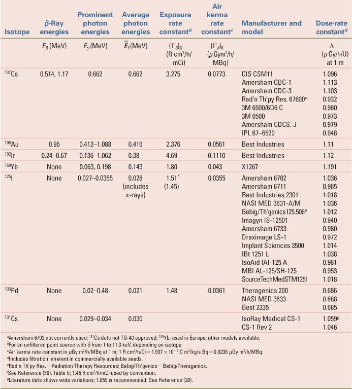
historical HVL and TVL are being replaced with the refined concepts of first HVL1 and TVL1 and equilibrium HVLe and TVLe that account for spectral changes with depth. The “equilibrium” notation (e) denotes the reduction achieved at greater depths (after 1/100th reduction in intensity) where dosimetry equilibrium is achieved; the notation “first” denotes reduction in the first layers of material (before 1/100th reduction in intensity) before equilibrium dosimetry is established. Shielding data for several brachytherapy radionuclides are available (39). 137Cs, 198Au, 192Ir, and 169Yb emit higher energy γ-rays with greater penetrability and present more radiation protection challenges than 103Pd, 125I, and 131Cs, that emit less penetrating lower-energy x-rays. Table 17.1 shows that TVLe is about three times HVLe for 137Cs, 192Ir, 198Au, and 169Yb; but this is not true for the less penetrating 103Pd, 125I, and 131Cs. The large separation in air between the source and attenuating material positions inherent in the shielding definitions of either “equilibrium” or “first” HVL and TVL do not occur in brachytherapy applicator treatment geometries. In applicators, the source beam is wide and shields are very close to the source. The degree of attenuation actually achieved when a lead shield is placed very close to a brachytherapy source can differ markedly from that expected from the application of shielding definitions of either “equilibrium” or “first” HVL and TVL.
historical HVL and TVL are being replaced with the refined concepts of first HVL1 and TVL1 and equilibrium HVLe and TVLe that account for spectral changes with depth. The “equilibrium” notation (e) denotes the reduction achieved at greater depths (after 1/100th reduction in intensity) where dosimetry equilibrium is achieved; the notation “first” denotes reduction in the first layers of material (before 1/100th reduction in intensity) before equilibrium dosimetry is established. Shielding data for several brachytherapy radionuclides are available (39). 137Cs, 198Au, 192Ir, and 169Yb emit higher energy γ-rays with greater penetrability and present more radiation protection challenges than 103Pd, 125I, and 131Cs, that emit less penetrating lower-energy x-rays. Table 17.1 shows that TVLe is about three times HVLe for 137Cs, 192Ir, 198Au, and 169Yb; but this is not true for the less penetrating 103Pd, 125I, and 131Cs. The large separation in air between the source and attenuating material positions inherent in the shielding definitions of either “equilibrium” or “first” HVL and TVL do not occur in brachytherapy applicator treatment geometries. In applicators, the source beam is wide and shields are very close to the source. The degree of attenuation actually achieved when a lead shield is placed very close to a brachytherapy source can differ markedly from that expected from the application of shielding definitions of either “equilibrium” or “first” HVL and TVL.
Table 17.1 Physical Properties of Radionuclides Currently Used in Brachytherapy | |||||||||||||||||||||||||||||||||||||||||||||||||||||||||||||||
|---|---|---|---|---|---|---|---|---|---|---|---|---|---|---|---|---|---|---|---|---|---|---|---|---|---|---|---|---|---|---|---|---|---|---|---|---|---|---|---|---|---|---|---|---|---|---|---|---|---|---|---|---|---|---|---|---|---|---|---|---|---|---|---|
| |||||||||||||||||||||||||||||||||||||||||||||||||||||||||||||||
The curie (Ci), the historical measure of radioactivity, was originally defined as the number of α-particles per unit time emitted by radon in secular equilibrium with 1 g of 226Ra; it is now defined as 3.7 × 10¹⁰ disintegrations per second. The becquerel (Bq)—one disintegration per second (1 Ci = 3.7 × 10¹⁰ Bq)—is the SI unit of activity (38). The curie and becquerel are used in nuclear medicine and health physics to describe amounts or quantities of unencapsulated radionuclides. The curie and becquerel are used in brachytherapy physics only as shorthand notations to specify approximate content quantities of encapsulated radioactive materials, for example, 10 mCi or 37 MBq, or to describe quantities of radioactive materials possessed under a regulatory license. For example, a license may list the maximum possession limit of a radionuclide, for example, 125I, in either curies or becquerels. For brachytherapy physics of encapsulated sources, encapsulated content quantities, in curie and becquerel, used historically to describe and identify sources have been replaced by other parameters, discussed later, that more accurately describe strengths of encapsulated sources.
The specific activity of pure radionuclides is the activity per unit mass (Ci/g) and is the product of Avogadro’s number, N0 (6.023 × 10²³ atoms per gram atomic weight), and the decay constant, λ, divided by atomic weight, M. Radionuclides such as 192Ir, exhibiting high specific activity (low atomic weight and short high-life) and high physical density, permit construction of encapsulated small (0.59 × 10 mm) dimension, high activity (12 Ci [444 GBq]) HDR sources.
The apparent activity, Aapp, of an encapsulated source is the activity of an unencapsulated source that produces the same exposure rate in air,  , at a known distance in the same geometry as that produced by the encapsulated source. The content activity, A, in the encapsulated source exceeds Aapp, because the capsule attenuates not only most of the β-rays, but also some of the γ-rays emitted from the radioactive material inside the capsule. As a concept, Aapp, is still useful in describing how encapsulation of a known activity of a radionuclide in a capsule of particular design decreases the exposure rate or reference air kerma rate at locations around the capsule to give an exposure rate equivalent to that of another source. However, use of Aapp as a method of source strength specification and in computational quantities in brachytherapy is discouraged (40). , at a known distance in the same geometry as that produced by the encapsulated source. The content activity, A, in the encapsulated source exceeds Aapp, because the capsule attenuates not only most of the β-rays, but also some of the γ-rays emitted from the radioactive material inside the capsule. As a concept, Aapp, is still useful in describing how encapsulation of a known activity of a radionuclide in a capsule of particular design decreases the exposure rate or reference air kerma rate at locations around the capsule to give an exposure rate equivalent to that of another source. However, use of Aapp as a method of source strength specification and in computational quantities in brachytherapy is discouraged (40). |
An important parameter of any radionuclide is the quantity of radiation (γ-rays, characteristic x-rays, β-rays, bremsstrahlung) emitted per unit time per amount of radioactive material. The concept has a long history that has suffered from notational confusion and inconsistent application. In early literature the concept was generally called the k factor; its value for each radionuclide was not known well. In 1962, the term specific γ-ray constant, Γ, was defined (41). The specific γ-ray constant, Γ (which by definition applied to sources of specific encapsulation because of photons of energy greater than δ), was usually expressed in roentgen square centimeter per hour per millicurie (R cm2/h/mCi). The definition notes, “[I]t is assumed that the attenuation in the source and along its length is negligible” (41).
The specific γ-ray constant definition did not include the exposure rate of the lower-energy-emitted x-rays, and a new term, the exposure rate constant, was adopted in 1971 (42). The exposure rate constant, (Γδ)x (in R cm2/h/mCi), which measures the ability of photons from the radionuclide to transfer energy to air, is given by the quotient of l2 (dX/dt)δ by A (in millicuries), where (dX/dt)δ is the exposure rate because of photons of energy greater than δ at a distance l (in centimeters) from a point source of activity A. In its original definition, for radionuclides other than 226Ra, it was defined for an ideal unencapsulated point source; it includes all photon radiation, both nuclear and nonnuclear (characteristic x-rays and bremsstrahlung radiation arising from conversion electrons), with energies greater than δ, where δ often is 11.3 keV, and depends on the application. The original definition applied filtration only for 226Ra for a 0.5-mm thick (10% iridium, 90% platinum) wall, (Γδ)x = 8.25 R cm2/h/mg. For 226Ra tubes with 1-mm iridioplatinum walls, the constant is 7.71 R cm2/h/mg. Note that the same mathematical symbol, Γ, is used for these two differing concepts: specific γ-ray constant and exposure rate constant. Reports on the specific γ-ray constant, exposure rate constant, and filtered exposure rate constant of 192Ir contain calculations that clarify the concepts (43,44). Contrary to its original definition, in current popular usage, the exposure rate constant (Γδ)x is frequently stated for sources of certain design and specific encapsulation. The popular use assumes that in a source of finite size, attenuation and scattering occur and annihilation radiation and external bremsstrahlung may be produced, requiring significant corrections. When used in this manner, the source model or specific encapsulation must be stated but, unfortunately, often is not.
Since 1980 the air kerma rate, [k with dot above]air, has been recommended to replace exposure rate in air as the fundamental concept for brachytherapy absorbed dose calculations (45). The air kerma rate is:
An exposure of 114.5 R, when multiplied by the ratio  (0.876 cGy/R) is equivalent to an air kerma of 1 Gy. [k with dot above]air is commonly expressed in units of μGy/h or cGy/h. (0.876 cGy/R) is equivalent to an air kerma of 1 Gy. [k with dot above]air is commonly expressed in units of μGy/h or cGy/h. |
The air kerma rate constant, (Γδ)K, as originally defined, is a fundamental property of the unencapsulated idealized point source and neglects activity distribution, self-absorption, and filtrations in encapsulated sources. Hence, it was defined with the same restrictions as the exposure rate constant (46). For 226Ra, the air kerma rate constant, (Γδ)K, for 0.5-mm iridioplatinum filtration is 7.227 cGy cm2/h/mg or 7.227 μGy m2/h/MBq. In SI units, this is 2.0075 fGy m2/s Bq. The reference air kerma rate, [k with dot above]1, measured in μGy m2/h, at a known reference distance (1 m), on the perpendicular bisector of a source is the SI recommended measure of source strength (45). [k with dot above]1 can be expressed for the entire source (μGy m2/h) at 1 m or per unit source length (per cm; in μGy m2/h/cm). In the United States a related concept recommended by the AAPM (47), air kerma strength, SK, in μGy m2/h at 1 m, is the product of the air kerma rate in free space, [k with dot above]air, at distances l, and the distance squared, l2, is given by:
The air kerma strength, SK, is numerically equal to the reference air kerma rate, [k with dot above]1, but its unit (μGy m2/h), includes distance squared (m2). By definition, 1 μGy m2/h at 1 m (or 1 cGy cm2/h at 1 cm) is 1 U, a unit of convenience. However, air kerma strength, SK, is not a recommended SI term, and its unit, U, is not a recommended SI unit (38). Nevertheless, SK is now the recognized parameter for encapsulated source strength specification and subsequent absorbed dose calculations in the United States.
The original parameter of interest in brachytherapy, from which one extracted the absorbed dose rate in the tissue medium, was the exposure rate in air, X/Δt, in R/h, at some distance, l, from a point source encapsulated radionuclide. This is given by:
where (Γδ)x, for a specific source filtration, is the specific γ-ray constant or exposure rate constant in R cm2/h/mCi. Aapp is its apparent activity in millicuries, and l is the distance in centimeters from the source to the point where the exposure rate is stated. For radium substitute sources, it was common practice to express apparent activity in millicuries of the source as being equivalent to milligrams of radium (mg Ra eq), for example, Aapp, equivalent (mg Ra eq). For example, the milligram radium equivalent of an equivalent radionuclide such as 137Cs is the mass in milligrams of 226Ra in equilibrium with its decay products
screened by 0.5-mm thick iridioplatinum wall that would yield the same exposure rate in air in scatter-free conditions as produced by an encapsulated 137Cs source at the same distance and in the same geometry. It follows that:
screened by 0.5-mm thick iridioplatinum wall that would yield the same exposure rate in air in scatter-free conditions as produced by an encapsulated 137Cs source at the same distance and in the same geometry. It follows that:
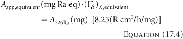
Depending on the design and encapsulation (doubly encapsulated in iridioplatinum or stainless steel), and, hence, an appropriate choice of (Γδ)X,equivalent, for example, 3.226 R cm2/h/mCi, a 137Cs source containing ∼25.57 mCi (946.2 MBq) yields an exposure rate equivalent to a 10 mg 226Ra source with 0.5-mm iridioplatinum walls. For exposure and absorbed dose calculations, if the Aapp, equivalent of the equivalent radium substitute source is expressed in milligram radium equivalents, the specific γ-ray constant or exposure rate constant to be used is that of 226Ra, Γ = 8.25 R cm2/h/mg, for a 0.5-mm thick wall of iridioplatinum (10% iridium, 90% platinum), from which the equivalency was drawn, not that of the radionuclide actually used (e.g., 137Cs) for the treatment. Misunderstanding of this point has led to the mistreatment of numerous patients. While physicists have abandoned the use of milligram radium equivalency for source strength specifications, the concept of milligram hours, mgh, is still used clinically by some radiation oncologists because it is a simple clinical concept with a long clinical history. Indeed, the current American Brachytherapy Society Cervical Cancer Brachytherapy Task Group still retains LDR prescriptions in milligram-hours (48).
The fundamental parameter of interest in brachytherapy is neither source activity nor exposure rate; it is the absorbed dose rate to the medium [D with dot above]med—commonly water or muscle. Simplistically, neglecting the perturbing influences of source and medium, one obtains the absorbed dose rate to the medium by first calculating the exposure rate in air,  , and then multiplying by an appropriate factor, fmed, that converts the exposure in air to absorbed dose in the medium. The fmed factor is the product of , and then multiplying by an appropriate factor, fmed, that converts the exposure in air to absorbed dose in the medium. The fmed factor is the product of  (the average energy required to produce an ion pair in dry air divided by the charge of an electron; the quotient is 33.97 J/C [joules per coulomb] or 0.876 cGy/R), and the ratio of mean mass energy transfer coefficients (μtr/ρ)med (1 – g)/(μtr/ρ)air (1 – g), where g is the very small fraction of the energy transferred that leads to bremsstrahlung radiation. Generally, for the brachytherapy radionuclides, g is <0.3% for both water and air and is usually neglected; hence, the ratio can be expressed as (μen/ρ)med/(μen/ρ)air. For most radionuclides with photon energies between 180 keV and 4 MeV, this ratio of mean mass energy absorption coefficients for water to air is almost constant at 1.11. For 125I, it is 1.02. Hence, fmed equals 0.876 (μen/ρ)med/(μen/ρ)air cGy/R. As shown in Table 17.1, values range from approximately 0.879 for 131Cs to 0.973 for 137Cs. (the average energy required to produce an ion pair in dry air divided by the charge of an electron; the quotient is 33.97 J/C [joules per coulomb] or 0.876 cGy/R), and the ratio of mean mass energy transfer coefficients (μtr/ρ)med (1 – g)/(μtr/ρ)air (1 – g), where g is the very small fraction of the energy transferred that leads to bremsstrahlung radiation. Generally, for the brachytherapy radionuclides, g is <0.3% for both water and air and is usually neglected; hence, the ratio can be expressed as (μen/ρ)med/(μen/ρ)air. For most radionuclides with photon energies between 180 keV and 4 MeV, this ratio of mean mass energy absorption coefficients for water to air is almost constant at 1.11. For 125I, it is 1.02. Hence, fmed equals 0.876 (μen/ρ)med/(μen/ρ)air cGy/R. As shown in Table 17.1, values range from approximately 0.879 for 131Cs to 0.973 for 137Cs. |
A more complete expression reflecting the perturbing influence of source and medium in the radial dimension is:
where T(r) represents radial attenuation and radial multiple scattering effects in the medium and  (r) is an anisotropy constant to account for any source radial anisotropy—both topics are discussed later. (r) is an anisotropy constant to account for any source radial anisotropy—both topics are discussed later. |
Similar expressions exist using the air kerma rate. The air kerma rate in air is multiplied by the ratio of the mean mass-energy absorption coefficients of water or muscle and air, previously described, to yield the absorbed dose rate in the medium:
Including the radial attenuation and multiple scattering in the medium and possible source radial anisotropy, the dose rate in a medium is expressed thus:
This simple model or its analog (Equation 17.5) was widely used in computer algorithms for dose calculations in brachytherapy in the 1980s.
In 1990, a new dose formulation that describes two-dimensional (r,θ) (Fig. 17.1) dose distribution for 192Ir and 125I was introduced (49). TG-43 adopted and recommended this formulation and expanded it in 1995 to include 103Pd seed sources. The methodology, generally called the TG-43 formalism (50), its update (7), erratum
(8), and supplement (6) are widely used for brachytherapy seed dose calculations. Using the formulation of TG-43, the dose rate in a medium is:
(8), and supplement (6) are widely used for brachytherapy seed dose calculations. Using the formulation of TG-43, the dose rate in a medium is:
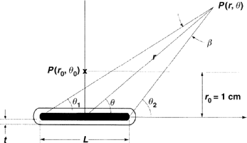 Figure 17.1. TG-43 schema for calculating the dose at point P(r,θ) from a line source of length L with wall thickness t. The point P(r0,θ0) is the normalization point (r0 = 1 cm) on the bisector for normalization of the radial dose function g(r), the geometry factor G(r, θTG–43), and the anisotropy function F(r, θTG–43). Note that in TG-43 formalism, θTG–43 is the angle of the radius, r, with respect to the axis, z. (Historically, θ is the angle of the radius, r, with respect to h, the bisector of the source; see Fig. 17.4 for comparison). (Reprinted with permission from Medical Physics (Copyright 2004); Rivard et al. Update of AAPM Task Group Report No.43 Report: a revised AAPM protocol for brachytherapy dose calculations. Med Phys. 2004;31:633–674.) |
where SK is the air kerma strength in cGy cm2/h, Λ is the dose-rate constant, in cGy/h/U, G(r, θ)/G(1,π/2) is the geometry factor, without units, g(r) is the radial dose function, without units, and F(r,θ) is the anisotropy function, without units.
The dose-rate constant, Λ, is defined as the absorbed dose rate to water, [D with dot above](r0,θ0), at a distance of 1 cm on the transverse axis of a unit air kerma strength source, SK, in a water phantom. It includes the effects of source self-attenuation and filtration, analogous to the prior discussion on exposure rate constants for specifically encapsulated sources. Mathematically,
The geometry factor, G(r,θ), accounts for the variation of relative dose only because of the spatial distribution of activity within the source, ignoring absorption, and scattering in the source. Two models, a point source, G(r,θ) = r-2, and a line source, G(r,θ) = β · (L r sin θ)-1, where L is the source active length and β is the angle subtended by the active source with respect to the point (r,θ). Table V of TG-43 offers values of G(r, θ)·r2 for a 3-mm line source (50). For r = 1 cm, typical values range from 1.023 for θ = 0 degree to 0.9926 for θ = 90 degrees (50).
The radial dose function, g(r), accounts for the absorption and scatter in the medium along the transverse axis of the source. Specific to each source and its design, values range from 1.29 at 0.5 cm to 0.0893 at 5 cm for a certain design of 103Pd source to 0.994 at 0.5 cm to 0.891 at 9 cm for an 192Ir source. TG-43 (7,8) offers explicit equations that are given for numerous sources of different designs, and new source design dosimetry reports (11,17) usually include g(r) values. Taylor and Rogers (51) report an improved fitting function for g(r) for 18 125I seed models and 9 103Pd seed models.
The anisotropy function, F(r,θ) accounts for the anisotropy (nonuniformity) of the dose distribution around the source. TG-43 offers tabular values for specific source designs. For example, for an 192Ir source, values range from 0.806 (at 1 cm, 0 degree) to 1.00 (at 9 cm, 90 degree).
If one applies a point source approximation, the two-dimensional anisotropy function F(r,θ) is replaced by the one-dimensional anisotropy factor φan(r). This factor is the ratio of the absorbed dose rate at distance r, averaged with respect to solid angle, to the absorbed dose rate on the transverse axis at the same distance r. For example, for a Model 6711 125I seed, values range from 0.944 at 1 cm to 0.901 at 7 cm. A simpler approximate concept, independent of distance, is the anisotropy constant,  (r). For the same seed described, the value is 0.93. Commercial isodose computation systems now support the TG-43 dosimetry model (35). There is no way this limited discussion of TG-43 can do justice to the volumes of literature that TG-43 and its revisions has evoked—it is the second most cited article in Medical Physics literature (52). Readers are encouraged to consult the original document (50), its update (7), erratum (8), and supplement (6) for a thorough discussion of concepts. (r). For the same seed described, the value is 0.93. Commercial isodose computation systems now support the TG-43 dosimetry model (35). There is no way this limited discussion of TG-43 can do justice to the volumes of literature that TG-43 and its revisions has evoked—it is the second most cited article in Medical Physics literature (52). Readers are encouraged to consult the original document (50), its update (7), erratum (8), and supplement (6) for a thorough discussion of concepts. |
As noted, the TG-43 formalism was revised (and the revision subsequently corrected) in 2004 (7,8). The revision was prompted for several reasons, including improved source calibrations at NIST and a dramatic increase in the number of seeds with different designs marketed and for which dosimetry studies were performed. This revised formalism, TG-43U1, is now on commercial isodose computers. With some trepidation of committing sins of omission, a most limited comparison of the two protocols is offered.
First, TG-43U1 contains no new 192Ir seed data—data in the original TG-43 report is valid.
TG-43U1 expands the three permanent seed recommended data sets (two models of 125I seeds, one model of 103Pd seed) to eight (six models of 125I seeds, two models of 103Pd seed) (7,8). Some changes are notational, adding subscripts (e.g., “P” for point, “L” for line) to the geometry factor, G(r,θ), now GP(r,θ) or GL(r,θ), as required. Other changes are minor, such as clarifying that SK is in vacuo, meaning that during its measurement corrections are made for air attenuation. Unchanged are definitions of the dose-rate constant, Λ, and the anisotropy function φan(r) (but continued use of the anisotropy constant  (r) is not recommended). The most significant changes are the inclusion of the radial dose function g(r) for both a point source and a line source, changes in the consensus data set for the three original permanent seed models in TG-43, and the inclusion of five more consensus data sets for new permanent seeds (7,8). Table 17.2 offers examples of the TG-43U1 data for the two original permanent seed models 6711 and 200. This table is included to stress that the dosimetry for the two original permanent seeds models 6711 and 200 was changed and that the 2007 supplement (6), TG-43U1S1, contains new data for an additional seven 125I and one new 103Pd source. Readers must study TG-43 (50), TG-43U1 (7,8), and the supplement (6) to fully appreciate all source dosimetry. (r) is not recommended). The most significant changes are the inclusion of the radial dose function g(r) for both a point source and a line source, changes in the consensus data set for the three original permanent seed models in TG-43, and the inclusion of five more consensus data sets for new permanent seeds (7,8). Table 17.2 offers examples of the TG-43U1 data for the two original permanent seed models 6711 and 200. This table is included to stress that the dosimetry for the two original permanent seeds models 6711 and 200 was changed and that the 2007 supplement (6), TG-43U1S1, contains new data for an additional seven 125I and one new 103Pd source. Readers must study TG-43 (50), TG-43U1 (7,8), and the supplement (6) to fully appreciate all source dosimetry. |
In summary, four methods have been used to specify the strength of a brachytherapy source. The two historical methods, apparent activity, Aapp (mCi), and Aapp, equivalent (mg Ra eq) are conceptually valid, and useful in understanding the historical development of brachytherapy, but are no longer recommended for source strength specification. The reference air kerma rate, [k with dot above]air(μGy m2/h at 1 m or μGy/h at 1 m per unit source length), is the recommended SI methodology, and is used in Europe (38). The alternate air kerma strength, SK (U, μGy m2/h or cGy cm2/h) is used in the United States. Commercial source “strengths” may be stated by any or all of these methods. Expressing source “strength” as absorbed dose rate at a reference distance (1 m), [k with dot above]air(μGy m2/h or μGy/h per unit length) (Europe) or air kerma strength, SK (μGy m2/h or U) (United States), for a specified filtration, avoids any confusion associated with apparent or equivalent activities and the associated constants.
Table 17.2 Example Data from Task Group 43U1 and Task Group 43U1S1; Partial Data Sets for Models 6711, 6733 and Models 200, 2355 | ||||||||||||||||||||||||||||||||||||||||||||||||||||||||||||||||||||||||||||||||||||||||||||||||||||||||||||||
|---|---|---|---|---|---|---|---|---|---|---|---|---|---|---|---|---|---|---|---|---|---|---|---|---|---|---|---|---|---|---|---|---|---|---|---|---|---|---|---|---|---|---|---|---|---|---|---|---|---|---|---|---|---|---|---|---|---|---|---|---|---|---|---|---|---|---|---|---|---|---|---|---|---|---|---|---|---|---|---|---|---|---|---|---|---|---|---|---|---|---|---|---|---|---|---|---|---|---|---|---|---|---|---|---|---|---|---|---|---|---|
|
Users must apply great caution when using any source strength for absorbed dose calculations either manually or from parameters entered into computers, as incorrect use of one of the four parameters of strength (Aapp [mCi], Aapp, equivalent [mg Ra eq], Aapp [MBq], SK [U, μGy m2/h, or cGy cm2/h]) with incorrect use of one of the four corresponding constants (exposure rate constant, (Γδ)x, in R cm2/h/mCi, for specific filtration; exposure rate constant of 226Ra, with 0.5-mm iridioplatinum wall, (Γδ)x,226Ra, 8.25 R cm2/h/mg; air kerma rate constant, (Γδ)K, in μGy/h/MBq, for a specific filtration; and finally, dose-rate constant, Λ, in cGy/h/U), yields an incorrect absorbed dose calculation.
The correct products of these two key parameters are: (a) Aapp, (mCi) · (Γδ)x (R cm2/h/mCi) for specific filtration; (b) Aapp, equivalent (mg Ra eq) · 8.25 R cm2/h/mg, exposure rate constant of 226Ra filtered by 0.5-mm iridioplatinum; (c) Aapp,(MBq), · (Γδ)K (μGy m2/h/MBq), for a specific filtration; and (d) SK (U) · Λ (cGy/h/U) for a specific filtration. Other products, for example, Aapp (mCi) · Λ (cGy/h/U) or SK (U) · (Γδ)X,equivalent (R cm2/h/mg) are incorrect and will yield incorrect absorbed dose calculations. All four correct products must be appropriately multiplied by other terms, previously described, to determine the absorbed dose rate at a point (r,θ) near the source.
Source activity stated in air kerma strength, SK, in μGy m2/h or U, for a specified filtration, mathematically, is the product of an air kerma rate constant (in μGy m2/h/MBq) for a specific filtration and the corresponding apparent activity (in MBq). Use of SK, however, requires no knowledge of either term, and separation of SK into two pseudo terms is discouraged. However, some computer algorithms require separate values of the two parameters, and dummy values may be used as long as they yield the proper product for SK. It is important to determine whether the algorithm makes a correction for source filtration (53). If it does, the dummy values must be selected so that after the source filtration correction, the product of the two terms yields the correct value of SK.
Radionuclides
Numerous radionuclides (e.g., phosphorus 32, cobalt 60, selenium 75, strontium 90, yttrium 90, palladium 103, ruthenium 106, iodine 125, cesium 131, cesium 137, samarium 145, ytterbium 169, thulium 170, tantalum 182, gold 198,
iridium 192, radon 222, radium 226, americium 241, californium 252) have either been commercially marketed or proposed, investigated (and in some instances, abandoned) for various forms (LDR, HDR, intravascular, infusion, or eye plaques) of brachytherapy. The historical significance of 226Ra and radon 222 (222Rn) is briefly reviewed but attention is concentrated on 137Cs, 192Ir, 198Au, 125I, 103Pd, 131Cs, and 169Yb use for conventional LDR intracavitary or interstitial brachytherapy. Tables 17.1 and 17.3 list useful physical parameters of these seven radionuclides.
iridium 192, radon 222, radium 226, americium 241, californium 252) have either been commercially marketed or proposed, investigated (and in some instances, abandoned) for various forms (LDR, HDR, intravascular, infusion, or eye plaques) of brachytherapy. The historical significance of 226Ra and radon 222 (222Rn) is briefly reviewed but attention is concentrated on 137Cs, 192Ir, 198Au, 125I, 103Pd, 131Cs, and 169Yb use for conventional LDR intracavitary or interstitial brachytherapy. Tables 17.1 and 17.3 list useful physical parameters of these seven radionuclides.
Table 17.3 Properties of Somea Radionuclides Used in Brachytherapy | |
|---|---|
|
226Ra is excluded from Tables 17.1 and 17.3 but deserves limited mention because of its historical importance. Details of 226Ra and 222Rn sources were previously described (33). The key 226Ra parameter to remember is the well-known constant, Γ = 8.25 R cm2/h/mg, for a 0.5-mm thick wall of iridioplatinum (10% iridium, 90% platinum).
The relatively long half-life (30 years) and medium energy (0.66 MeV) of the nearly monoenergetic 137Cs made it a popular substitute for 226Ra. Most facilities have disposed of their 137Cs needles but a few facilities still perform LDR gynecological brachytherapy from a permanent inventory of 137Cs tubes. The dosimetry of source models Amersham CDCS-J and 3M 6500/6D6 C (53,54), Radiation Therapy Resources 67–800 (55), CDC miniatures (56), CIS CSM11 (57), and Amersham CDCS-M (58) are reviewed by Liu et al. (59) with useful TG-43 data (effective attenuation coefficients, radial dose functions, and anisotropy functions) for the dosimetry of certain models. Melhus and Rivard report new Monte Carlo dosimetry for 137Cs sources (60), whereas Vianello and de Almedia investigated photon fluence nonuniformity near linear 137Cs sources (61). Interest in conventional LDR brachytherapy with 137Cs sources is sufficient to support the market for a new model 67–6520 137Cs source (Manufacturer: Eckert & Zigler Isotope Products, Valencia, CA; Vendor: Radiation Products Design, Albertville, MN) (62). Each source tube (Fig. 17.2) contains a labeled ceramic rod as the active element surrounded by two stainless steel encapsulations—each of which is of welded construction. The standard size tube is 20 mm long by 3.05 mm diameter, and the inner ceramic active element is 14.8 mm long by 1.52 mm diameter.
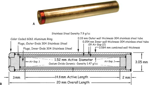 Figure 17.2. A: The Eckert & Zigler Isotope Products (EZIP) brachytherapy 137Cs source. Serial numbered, color-coded sources are available from 5 mg Ra equivalent to 40 mg Ra equivalent, in 5 mg Ra equivalent increments. (Reprinted with permission from Radiation Products Design, Inc., Albertville, MN 55301.) B: Construction details of the tube source. It contains a cesium labeled ceramic rod as the active element surrounded by two stainless steel encapsulations, each of which is of welded construction. (Reprinted with permission from Radiation Products Design, Inc., Albertville, MN 55301.) |
192Ir, with a modest half-life (73.83 days) and a complex spectrum of γ-ray energies (average energy 0.38 MeV) exhibits a high specific activity (450 Ci per g) suitable for 10 Ci (370 GBq) sources for HDR remote afterloaders (see Chapter 18). A wire coil is popular in Europe, and its dosimetry has been reported (63,64,65). A new method of modeling wires has been reported (64). In the United States, seeds with activities of tenths of millicuries to several millicuries, in nylon ribbons, are widely used for interstitial implants (66,67,68). Seed design varies by manufacturer but generally consists of a 0.3-mm diameter core of a mixture of 10% to 25% iridium and the rest platinum, coated with an additional 0.1-mm thickness of either pure platinum or stainless steel to form a 0.5-mm diameter seed ∼3 mm long. The sources are not considered sealed or encapsulated, as are other brachytherapy sources, and are subject to wipe test requirements different from encapsulated sources. Integrity of the coating must be maintained during any source manipulations to prevent removing the coating and releasing any undesired β-ray irradiation during use. Recommended dosimetry values are in TG-43 (50). Recent investigations have studied the effects of phantom material composition and size on 192Ir dosimtery (69,70). Glasgow et al. (71) investigated the feasibility of a low-cost permanent 192Ir seed.
198Au is the least popular of the seven radionuclides. A few universities with cyclotrons capable of producing 198Au have used it as an interstitial source for prostate, bladder, or brain
implants and it is commercially available. 198Au, with a short half-life (2.7 days) suitable for permanent implants, releases a dominant 0.412-MeV γ-ray that produces issues regarding personnel radiation exposure. The short half-life makes source production and distribution by commercial carriers more difficult; moreover, there is no NIST national calibration standard for 198Au. Hence these sources are not popular in the United States, but they do enjoy some popularity in Europe. The seeds or grains are approximately 2.5 mm long and 0.15 mm in diameter; the outer casing is 0.15-mm platinum capsule with the 198Au radioactive matrix inside. The dosimetry of 198 Au has been reported (72,73).
implants and it is commercially available. 198Au, with a short half-life (2.7 days) suitable for permanent implants, releases a dominant 0.412-MeV γ-ray that produces issues regarding personnel radiation exposure. The short half-life makes source production and distribution by commercial carriers more difficult; moreover, there is no NIST national calibration standard for 198Au. Hence these sources are not popular in the United States, but they do enjoy some popularity in Europe. The seeds or grains are approximately 2.5 mm long and 0.15 mm in diameter; the outer casing is 0.15-mm platinum capsule with the 198Au radioactive matrix inside. The dosimetry of 198 Au has been reported (72,73).
125I seeds have had limited use in temporary implants (breast) and eye plaques, but are popular for permanent implants in the prostate and lung. With a modest half-life (59.40 d), they emit a low-energy 35.5-keV γ-ray and x-rays with lower energies, 31.7 to 27.2 keV. The low energy allows local shielding with metal foils only a few tenths of a millimeter thick and allows numerous applications not available with other radionuclides. The original seed design, model 6702 (Medi-Physics, Arlington Heights, IL)—no longer sold—exhibited a highly anisotropic dose distribution. A subsequent design, model 6711 (also from Medi-Physics), exhibited a somewhat less anisotropic dose distribution. The popularity of prostate permanent seed implants led many manufacturers to enter the commercial market with seed designs with alleged improved dose distribution. The AAPM TG-43U1 update (7) includes the recommended dosimetry of six 125I sources: American Health models 6702 and 6711, Best Industries model 2301, North American Scientific Inc. model MED3631-A/M, Bebig/Theragenics Model I25.S06, and Imagyn Medical Technologies Inc. isotar IS-12501 (now discontinued). The TG-43U1 supplement (6) provides data for seven more seed designs: Amersham model 6733, Draximage model LS-1, Implant Science model 3500, IBt model 1251 L, IsoAid model IAI-125 A, Mentor model SL-125/SH-125, and SourceTech Medical STM125I. Dosimetry has been reported for four other models: SelectSeed (9), IsoSeed model I25.S17 (10), Bacon Co. (Buenos Aires, Argentina) model Braquibac (11), and Oncure/GE Healthcare (Arlington Heights, IL) model 9011 (12).
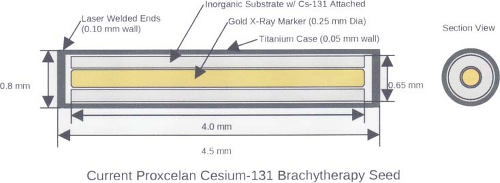 Figure 17.3. Model CS-1, Rev 2 Proxcelan 131Cs Brachytherapy Seed. (Reprinted with permission from IsoRay Medical. Inc. Richland, WA 99354–5411.) |
The history of the dosimetry of 125I seeds requires careful study and is beyond the scope of this chapter (50). The dosimetry of specific seed designs and their activities varies, and an absolutely thorough literature review with subsequent testing of applicable computer models is required before attempting to replicate the dosimetry (and clinical results) of the original 125I seeds. Moreover, over the years, and among different groups, there have been changes in clinical prescriptions. Hence, application of computer models for permanent seed implants requires very careful work and cross-comparison of dosimetry results among those using the same seed designs and the same isodose planning systems is strongly encouraged!
103Pd, a substitute for 125I, exhibits higher seed activity, correspondingly higher absorbed dose rate, and shorter half-life, all considered theoretically more radiobiologically advantageous for permanent implants in more rapidly growing cancers. 103Pd sources, with a short half-life (16.991 days), release characteristic x-rays with energies of 20.07 to 23.18 keV, with a few very weak photons with higher energies. Seeds typically have activities of up to 5 mCi, which produce higher dose rates than those achieved with conventional 125I seeds. The update of AAPM TG-43 included recommended dosimetry of two 103Pd sources: Theragenics Corporation model 200 and North American Scientific Inc. model MED3633 (7). The recent TG-43 supplement, TG-43U1SI, includes data for the Best Medical Model 2335 (5). Source designs (103Pd adsorbed onto silver beads, a coiled wire, and seeds without markers) have been described (74,75,76,77,78).
A 131Cs seed, Model CS-1 (IsoRay Medical, Inc., Richland, WA) for permanent implants was introduced in 2004. With the exception of its short half-life—9.69 days—it is similar to 125I, as its most prominent x-ray peaks are from 29 to 34 keV. Descriptions of its dosimetry and proposed therapeutic absorbed doses equivalent relative to 125I and 103Pd and dose-rate constants were reported (79,80,81). The modified seed design, Model CS-1 Rev. 2 (Fig. 17.3), was
introduced later and there are four dosimetry reports (15,16,17,18,19). However, TG-43 consensus dosimetry is not yet available. Originally used to treat prostate cancer and ocular melanoma, seeds are also available in flexible, bio-absorbable braided strands that can be attached to a bio-absorbable mesh that can be implanted to provide radiotherapy to surgical margins after resection of primary lung tumors. These strands have been used to treat head and neck tumors, chest wall tumors, and colorectal cancer.
introduced later and there are four dosimetry reports (15,16,17,18,19). However, TG-43 consensus dosimetry is not yet available. Originally used to treat prostate cancer and ocular melanoma, seeds are also available in flexible, bio-absorbable braided strands that can be attached to a bio-absorbable mesh that can be implanted to provide radiotherapy to surgical margins after resection of primary lung tumors. These strands have been used to treat head and neck tumors, chest wall tumors, and colorectal cancer.
Sources and Source Models in Vacuo
Two source models—static point and static line—are widely used to approximate the LDR dosimetry of sources. Karaiskos et al. offer a useful review of the limitations of each model as applied to commercial sources (85).
The point source model is the simplest. Lacking a perturbing surrounding medium (air, tissue, applicators, other sources), the radiation intensity around a point source decreases inversely with the square of the radial distance, as described in Equation 17.3, and is isotropic, equal in all directions. There are, of course, no treatments in vacuo and few truly spherical sources. However, sources (e.g., 198Au grains, 192Ir, 125I, 103Pd, and 131Cs seeds) are often modeled as point sources, as the physical orientation of their long (<0.5 cm) axis cannot always be discerned on radiographs or electronic images. TG-43U1 provides data sets for their representation as point sources (7,8). Radiation intensity near their welded or enclosed ends is less than the radiation intensity along the perpendicular bisector of the source. The radiation intensity at points at equal distance around the source, normalized to the radiation intensity at a reference distance on the radius bisecting the source, is called the anisotropy function F(r,θ) of the source. In the point source approximation, the two-dimensional anisotropy function F(r,θ) is replaced by the one-dimensional anisotropy factor φan(r). This anisotropy factor, φan(r), is the ratio of the absorbed dose rate at distance r—averaged with respect to solid angle—to the absorbed dose rate on the transverse axis at the same distance r. For example, for a Model 6711 125I seed, values range from 0.944 at 1 cm to 0.901 at 7 cm. A simpler approximate concept, independent of distance averaged and over 4π geometry, is anisotropy constant,  (r). TG-43 values of (r). TG-43 values of  (r) are 0.93 for 125I seed model 6711, 0.98 for 192Ir stainless steel-clad seeds, and 0.9 for 103Pd seed model 200 (Theragentics, Norcross, GA) (50). The point source model with use of an average anisotropy constant is reasonably accurate when large numbers of seeds are regularly distributed but randomly oriented in volume implants. However, if the seeds are in linear arrays, this simple expression of their anisotropy is inappropriate. Moreover, TG-43U1 no longer retains the anisotropy constant (r) are 0.93 for 125I seed model 6711, 0.98 for 192Ir stainless steel-clad seeds, and 0.9 for 103Pd seed model 200 (Theragentics, Norcross, GA) (50). The point source model with use of an average anisotropy constant is reasonably accurate when large numbers of seeds are regularly distributed but randomly oriented in volume implants. However, if the seeds are in linear arrays, this simple expression of their anisotropy is inappropriate. Moreover, TG-43U1 no longer retains the anisotropy constant  (r) as a concept (7). (r) as a concept (7). |
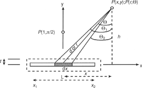 Figure 17.4. The historical schema for calculating the dose at point P(x,y) or P(r,θ) from either an unfiltered (center dark line) line source of length L or a filtered (outer dashed line) line source of half-thickness t. Note that θ is the angle of the radius, r, with respect to h, perpendicular to the axis, x. (see Fig. 17.1 for comparison). (Reprinted with permission from Oxford University Press (Copyright 1993); Modified from Arid EG, Williams JR. Brachytherapy. In: Williams JR, Thwaites DI, eds. Radiotherapy physics. Oxford: Oxford University Press, 1993:187–226, 192.) |
Most commercial computers with algorithms for seed implants offer a simple point source model for computer isodose calculations for seed arrays. The dosimetry at a point from an array of point sources is a straightforward summation—manually or by computer—of the radiation contribution at that point from each individual source.
An unfiltered line source model closely approximates the geometry of the early 226Ra sources, 137Cs tubes and needles, and segments of 192Ir wire. This simple geometry (Fig. 17.4) has been widely described in many mathematical notations. The description is offered in air kerma. For a source with air kerma rate constant (Γδ)K, an activity, A, and length L, the air kerma rate [k with dot above]air, at a point, P(x,y), and a distance, d, from the center of a source segment, dx, is given thus:
Expressing the point location P(x,y) in polar coordinates P(r, θ) where h is the perpendicular distance of point P from the source axis, it follows that as d = h/cos θ and x = h tan θ, in polar coordinates the integral becomes:
Following integration of the length of the source, the air kerma rate from all source segments is given by this well-known expression:
The air kerma rate [k with dot above]air at point P(r,θ) is the product of the linear activity (A/L), the air kerma rate constant, (Γδ)K, and the angle (θ2 – θ1) (in radian) subtended by the source, divided by the perpendicular distance, h, from point P to the source axis. It should be noted that in Figure 17.4 θ is the angle between radius r and the perpendicular distance, h, to the x-axis. In the TG-43 formalism (Fig. 17.1), the angle, β, subtended by the source is the complementary angle (90 degrees – θ), that is, the angle between the radius, r, and the x-axis. The component (θ2 – θ1)/hL is identical to the line source geometry factor G (r,θ) = β/(Lr · sin θ) in the TG-43 formalism. As expressed, this is for an unfiltered line source. However, while each segment of a line source contributes air kerma rate to a point following the basic inverse square law, near the line source the summation of the air kerma rates from each point source yields a variation that depends on the ratio of the angle subtended to the distance—not to the distance squared. When properly applied with other concepts, this equation is highly useful for dose estimates from line sources or pseudo-line sources (a linear string of point sources).
What is the dosimetry of a “point” versus a “line”? Figure 17.5 shows the variation in dose rate as a function of distance, on a log–log graph, for a 7.227 cGy/h/U (1 mg radium equivalent) point source, a 12-mm line source of the same activity, and a hypothetical source with an inverse (not inverse square) dependency on distance. Far from a line source, at distances beyond three times the length (36 mm in this example) of the source, the dose rates in air begin to approximate, to within ∼7%, those calculated from point source geometry. As the distance from the source increases, the line source more nearly approximates a point source. In the lower right corner, the two curves nearly coincide. The dosimetry of some implants requires knowledge of the doses within dimensions similar to the source lengths. Close to such sources, the inverse square law poorly estimates the dose. At close distances, 6 to 10 mm, the dosimetry exhibits a dependency that is similar to that of a source dependent on the inverse of the distance (1/r). Numerous patients have been mistreated because of misapplication of the inverse square law to estimate doses within 1 to 2 cm of line sources of these same lengths. Of course, the inverse square concepts correctly apply to each element of a line source; the true dependency of dose with distance is in the ratio [k with dot above]air(r, θ) = (Γδ)K[A/L][{θ2 – θ1}/h], which changes as h changes. At very close distances, that is, from approximately 0.5 to 0.1 cm from the sources the dosimetry is complex (86,87). Ballester et al. (88) report that 99% of electronic equilibrium is achieved at 3 mm for 137Cs, 2 mm for 192Ir, and 1 mm for 169Yb, and that electronic emissions become important (>0.5%) within 1.7 mm for 192Ir. Nath and Chen (89) reported on the silver florescent yield and its influence on the dose-rate constants of nine low-energy brachytherapy sources.
Related posts:

Stay updated, free articles. Join our Telegram channel

Full access? Get Clinical Tree


