11 Immobilization and Simulation
For radiobiologic reasons, the radiation dose is delivered in single or multiple daily fractions over a period of several weeks.1 During radiation therapy, it is important to make sure that the patient is treated in a reproducible manner on a day-to-day basis and that the same volume is irradiated during each fraction. Particularly with modern conformal techniques,2,3 in which the planned isodose line tightly surrounds the target volume, a mismatch between the planned dose distribution and the delivered dose may cause an underdosage to the target or overdosage to the surrounding normal tissues. This results in a suboptimal outcome for the patient. Furthermore, for treatment sites such as lung and liver, where larger margins are needed to account for respiratory motion, techniques such as deep inspiration breath hold (DIBH),4 robotic tracking, and respiratory gating (RG)5 are used to spare the normal tissues.
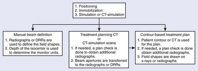
Radiotherapy simulation plays a crucial role in planning the strategy for the proper delivery of radiation dose. Important issues are decided during simulation, for example, how the patient will be positioned and immobilized and how the treatment beams will be directed. The flow chart in Fig. 11-1 shows some of the steps involved before treatment delivery. The simulation is carried out on a simulator or a virtual simulation is carried out on a CT simulator, and, to help in the patient’s alignment, the room also contains either wall-mounted or movable lasers.
The Conventional Simulator
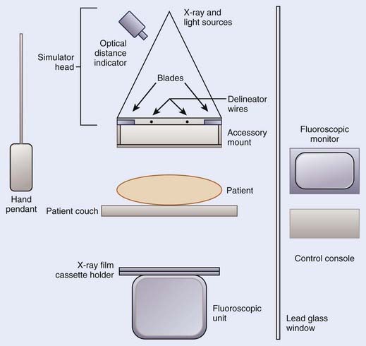
The purpose of a radiation therapy simulator is to mimic the radiation treatment unit, but, instead of a high-energy therapy beam, it produces low-energy, diagnostic quality x-rays for imaging. Most of the preparation for the treatment is done at a therapy simulator, which saves valuable treatment machine time. A simulator has most of the functionality of a treatment unit; the relevant components of a modern therapy simulator are shown in Fig. 11-2. The simulator head contains a diagnostic x-ray tube mounted at one end of a rotating gantry. At the other end are a film cassette holder and a fluoroscopic unit or digital imaging device.
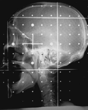
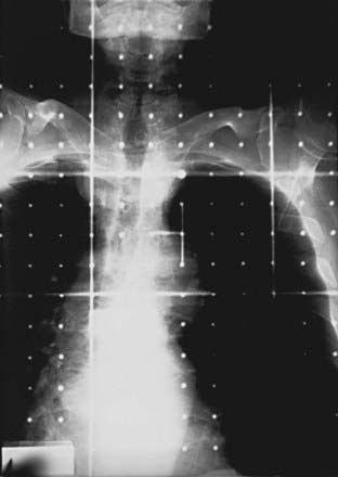
Housed in the simulator head is the collimator that has movable delineator (cross) wires and blades (jaws). On the simulator image, the delineator wires are projected as straight lines that define the field size. The blade positions determine the image size. A field localization light in the head projects the crosshairs and the delineator wires on the patient’s skin, which help in positioning the patient. The optical distance indicator measures the depth of the isocenter. The collimator includes an accessory mount that allows the treatment accessories, such as the block tray or the electron cones, to be mounted on the simulator. A gridded graticule tray with radiopaque markers provides a scale for measurement on the film. Fig. 11-3 shows a lateral head-and-neck radiograph on which the delineator wires, the crosshairs, and the graticule markers are projected. Fig. 11-4 is an anterior-posterior simulation film for a patient with lung cancer.
Computed Tomography Scanner and Spiral Computed Tomography Scanner
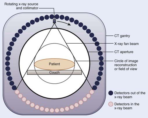
Since the first CT images obtained by Hounsfield,6 CT imaging has experienced rapid development. The major advancements have been in the area of image quality and scan time reduction. A fourth-generation CT scanner is shown schematically in Fig. 11-5. The x-ray tube and the collimator assembly rotate around the patient, and the intensities of the transmitted radiation reaching the detectors are recorded. Either a solid scintillation detector (bismuth germanate, cesium iodide, cadmium tungstate) array or a gas-filled (xenon or xenon-krypton) array is used for the detection. The transmission data are stored in the computer, and the image is reconstructed based on the attenuation information. The linear attenuation coefficients are converted into CT numbers, and the image is displayed on a video monitor. The CT numbers for the pixels are expressed in Hounsfield numbers and are related to linear attenuation coefficients:
where H is the CT number, µ is the linear attenuation coefficient for the pixel under analysis, and µw is the linear attenuation coefficient of water. The CT numbers in a scan range from −1000 to approximately +1000, with the CT number for water set at zero. A CT number of −1000 corresponds to air, and a CT number of +1000 is for very dense bone.
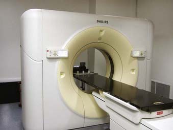
To obtain the volumetric data on a conventional CT scanner, after each scan the patient couch is translated to the new scan position. Because of the patient’s breathing and involuntary movement of the internal organs, motion artifacts are present unless special precautions are taken. In a spiral or helical CT scanner, the patient is transported through the gantry in synchrony with continuous data acquisition over a multitude of circular (360°) scans. Mathematical schemes7 have been developed to reconstruct axial scans that are similar to the scans obtained with a conventional scanner.8 On a spiral scanner, a volume or a subvolume can be scanned in a short time, on the order of 30 seconds. Another important development is the use of multisection imaging. The single narrow fan beam of x-rays is broadened into a cone beam, and each detector is replaced with a row of detectors (4 to 64). These detector rows are aligned parallel to the axis of the patient. These multidetector scanners are capable of imaging up to 64 sections of body simultaneously.9 Fig. 11-6 shows a multislice large bore (85 cm) scanner, used for CT simulation. The data for the whole study can be acquired during a single breath hold, resulting in images without interscan motion. From the diagnostic point of view, this is significant for locating small structures such as small pulmonary nodules, with which respiratory motion can cause detection problems.10 From the radiation therapy perspective, the advantages of the spiral CT scanner compared with a standard scanner are the ability to collect CT data with the patient in the immobilized treatment position within a shorter time frame and to create coronal and sagittal reconstructions with finer details.
The requirements for a therapy CT scan are different from those for a diagnostic scan.10,11 Some of the requirements are: (1) the patient should be scanned in the treatment position (the couch top should be flat, similar to a treatment couch; the physical CT aperture diameter and circle of reconstruction [field of view] should be large enough to accommodate the patient in the treatment position; if an immobilization device will be used during the treatment, the patient should be scanned immobilized, but the device should be made of materials that do not cause CT artifacts; and the anterior and lateral isocentric lines and other landmarks are marked on the skin by taping radiopaque catheters or lead beads); (2) CT scans should be of high quality so that the disease, tissue at risk, and surrounding normal tissues can be identified clearly; (3) particularly for three-dimensional (3D) treatment planning, a volume scan is required in order to delineate the treatment volume in three dimensions; in the region of treatment volume, a contiguous set with 5-mm spacing or smaller should be used to make sure that the small tumor extensions and normal structures are not missed (closely spaced scans also allow better image reconstruction); (4) anterior-posterior and lateral scout views should be obtained with the CT images indexed to these (these views are helpful in comparing CT data with conventional simulation radiographs); (5) the CT scanning should be completed in a short time period so that the patient remains adequately immobilized during the CT data collection; (6) for the treatment planning scans in the thoracic region, the patient should be scanned under shallow-breathing condition. Although the breathing introduces some motion artifacts in the images and the image quality may be degraded slightly, the scans represent the condition of the patient during treatment. However, there are interventional techniques, such as active breathing control, deep inspirational breath-hold and respiratory gating, can minimize the effect of respiratory motion, as discussed later.
Virtual Simulation
During conventional simulation the oncologist relies on the plain radiographs for designing the treatment ports. At times, even with the help of MRI, CT, and other diagnostic information, it is difficult to draw these ports accurately on the films. In the mid-1980s, Sherouse and colleagues12–14 introduced the term virtual simulation to describe a computer-based simulation process. They developed a software package that allowed the user to carry out simulation at a computer workstation instead of at a real simulator. The advantage of this method compared with plain radiographs is that the target volumes and anatomic structures, outlined on the CT scans, are used to make the decision about the position of the isocenter, field sizes, beam directions, and shielding blocks. CT scans provide better visualization of the disease and normal tissues, resulting in better target coverage and normal tissue shielding. The virtual simulator system has the ability to display and execute all the functions of a conventional radiotherapy machine, including gantry, couch, and collimator control.
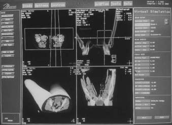
The CT data are obtained by scanning the patient in the immobilized treatment position. The CT scans are transferred to the planning system, and the skin, target, dose-limiting organs, and bony landmarks are contoured on the CT scans. The planner can view a 3D display of the patient model that consists of the skin, target, and other anatomic structures abstracted from the CT data. The contoured structures utilize different surface rendering and variable degree of transparencies to enhance the visualization. Fig. 11-7 shows a typical virtual simulator screen. Like a physical simulator, the virtual simulator allows the planner to adjust treatment parameters such as the gantry angle, field size, collimator angle, and so on. The beam’s-eye view (BEV) provides images that are similar to fluoroscopic images. The planner can select the treatment beam direction by watching projections of the target and surrounding structures in the BEV. The fields are then shaped by drawing the beam apertures using a mouse or other pointing device. At the end of the virtual simulation, digitally reconstructed radiographs (DRRs) are produced for each treatment field. A DRR15 is similar to a radiograph, but is designed by the computer based on the attenuation information derived from CT numbers in the original data set. The image quality of a DRR depends on the CT slice spacing—a smaller spacing results in a better DRR. The divergence of anatomic structures projected on a DRR is similar to that in the projection on a radiograph. The magnification of a DRR can be adjusted to match the simulation x-ray film. Along with the beam aperture and collimator, the target and other structures of interest are projected onto it. A list of beam, table parameters, and the templates for the beam modifiers are generated. Before the treatment, to verify the treatment ports, the localization port films can be compared directly with DRRs. Or, if the DRR quality is not good, the simulation radiographs in the treatment position can be taken and compared with the corresponding DRR. In many planning systems, the beam’s energy can be altered so that the DRR will look like a high-energy radiograph, making comparison to the port film simpler.
Computed Tomographic Simulator
The CT simulator is a whole-body CT scanner that is designed for radiation therapy simulation.16,17 It consists of three basic components: (1) a CT scanner, (2) an interactive workstation capable of virtual simulation, and (3) a mechanism for marking the beam portals on the patient’s skin. The patient is scanned in the treatment position and the CT images are transferred directly to virtual simulation workstation. The target volume and the relevant critical structures are outlined on the CT scans, the beam geometries are optimized, and DRRs are produced for the block definition and treatment verification.
The advantages of a CT simulator over a conventional simulator include: (1) the CT simulator allows for the visualization of the treatment volumes for the portal design; on a conventional simulation radiograph it is difficult to identify the target volume; (2) on DRRs the target volume and critical structures can be superimposed, and the treatment ports can be designed based on this; if needed, margins can be added around the target before outlining the shielding block; (3) the DRRs for the boost phase of the treatment can be produced from the same CT data set, without the need for the patient to be reimaged; (4) conventional simulators have physical limitations; for example, radiographs for the vertex field can not be obtained, whereas a virtual simulation software can produce these DRRs; (5) generally, a virtual simulation software package includes software to enhance the DRRs by adjusting the window and contrast levels. For example, the AcQsim (Philips Medical Systems, Cleveland, OH) package includes Digital Composite Radiograph (DCR), which groups CT numbers into ranges corresponding to bone, fat, muscle, and so on. The CT numbers in each category are modified by a weighting factor and redisplayed to provide greater enhancement of the specified tissue range18; Fig. 11-8A, B, and C show the regular DRR, DCRs for the bone and skin, respectively, for a head-and-neck patient; (6) the DRRs corresponding to each treatment field are generated; the magnification of the DRRs can be adjusted; cross hairs and grid points can be projected onto the DRR for direct comparison with the portal images.
However, there is a limitation of the CT simulator compared to the conventional simulator. Because of the finite bore size of the CT gantry, typically 65 to 70 cm, it is impossible to accommodate all patients and all patient positions. For example, extremely large patients, some patients in conventional position for breast cancer treatment, and patients requiring special immobilization devices may not be able to enter the 65- to 70-cm opening without compromising the position. A larger-opening 85-cm-bore, scanner has the potential to eliminate these problems. The image quality and the doses for the larger bore have been found comparable to the 70-cm-bore scanner.19 Fig. 11-6 shows an AcQsim CT simulator with 85-cm-bore gantry.
Interventional Strategies
With the use of 3D conformal radiation therapy (3DCRT) and intensity-modulated radiation therapy (IMRT), dose distributions have become highly conformal. Great care must be taken to make sure that the dose is delivered as planned; otherwise, the risk of marginal failure increases. There are two main causes of treatment inaccuracy: (1) uncertainty in defining the clinical target volume (CTV) and (2) variation in treatment geometry during treatment. If other imaging modality data sets such as MRI or PET are available, the image registration or fusion20 can be used to increase the accuracy of the CTV.
Active Breathing Control
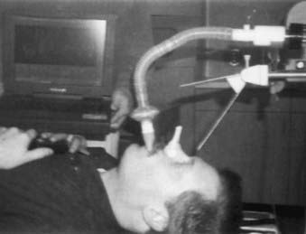
In this method, the patient’s nose is clamped and he or she breathes through an ABC apparatus via a mouthpiece, as shown in Fig. 11-9. The signal from the flow monitor is processed and a trace on the computer monitor displays the lung volume. During a particular sequence of the breathing cycle, at a predetermined flow direction and lung volume, a valve is activated to stop the airflow temporarily, resulting in the suspension of the breathing motion.21–23 The duration of the breath-hold is such that the patient can easily tolerate it. The amount of breath-hold a patient can tolerate depends on the disease site. For example, patients with lung disease can easily tolerate a breath-hold of 15 seconds near the end of normal inspiration, whereas for patients with Hodgkin’s disease and liver cancer, the breath hold ranges from 35 to 50 seconds when ABC is applied during inspiration.23 ABC can substantially reduce the treatment margins without the need to modify the therapy accelerator.
Deep Inspiration Breath Hold Technique
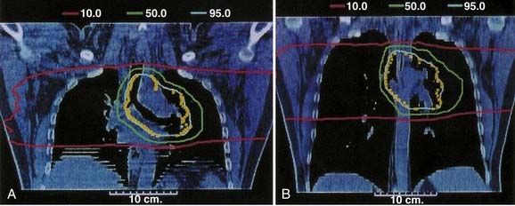
In this method the patient is coached on the technique of reproducible deep inspiration through the various phases of treatment planning and delivery.4,24,25 The DIBH uses a modified version of slow vital capacity maneuver26 to bring the patient to approximately 100% vital capacity, followed by a breath hold, which maintains the patient at that level for a prescribed period, during which the patient is simulated, CT-scanned, treated, and port filmed. The patient breaths through a mouthpiece connected to a spirometer control unit. A nose-clip is used to make sure that the patient breaths through the mouth. The spirometer measures the airflow and it is interfaced with a computer. The airflow is integrated to yield the lung volume as a function of time and is displayed on a computer monitor. The DIBH maneuver begins with quiet tidal breathing, followed by a slow deep inspiration, slow deep expiration, then a slow deep inspiration to the maximum limit and breath-hold. A training session is held to familiarize the patient with spirometer and to measure patient parameters, such as the tidal volume, vital capacity, and comfortable breath-hold duration. Some patients are unable to follow the directions and are unsuitable for DIBH. The technique has two advantages. First, the breath-hold minimizes tumor motion due to breathing. Second, it expands the patient lung to its maximum volume, pushing healthy lung tissue out of the primary radiation field and consequently reducing the fraction of the lung in the treatment beam. Fig. 11-10 compares the free breathing and DIBH treatment plans for a patient. The images are coronal planes through the isocenter for the same patient. Hanley et al.4 have found that DIBH can reduce the volume of the lung receiving more than 25 Gy by 30% compared to free-breathing plans. It is found to be highly reproducible. Patients could perform 10 to 13 breath holds in one session, with a comfortable breath-hold duration of 12 to 16 seconds.
Respiratory Gating
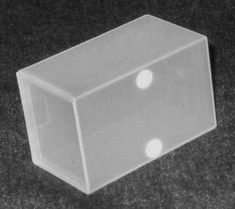
There are commercially available systems (for example, Real-time Position Management [RPM] Respiratory Gating; Varian Medical Systems, Palo Alto, CA) that permit breathing-synchronized fluoroscopy on a treatment simulator, acquisition of breathing-synchronized CT imaging, and gated treatment on a linear accelerator.5,27 The system consists of a charge-coupled-device (CCD) video camera attached to an infrared illuminator (Fig. 11-11) that tracks a patient’s respiratory motion by detecting reflected infrared light from two reflective markers on a lightweight block (Fig. 11-12). The block is placed on the patient’s chest or abdomen. The upper marker tracks the respiratory motion; the lower marker, separated by 3 cm from the upper marker, calibrates the system. The camera signal is processed by software. At the start of any session, whether simulation, CT, or treatment, the operator places the system into tracking mode for a few breathing cycles. This allows the system to determine the minimum and maximum vertical position of the upper marker. These values establish the scale of marker motion for subsequent display and for setting a gating threshold, as described later. At simulation, either amplitude or phase gating can be selected. For amplitude gating, the user adjusts the threshold levels that appear as two horizontal lines.
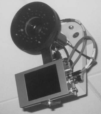
FIGURE 11-11 • Charge-coupled-device video camera attached to infrared illuminator for tracking the respiratory motion.
Simulation Process
Positioning of the Patient
Many issues are involved in defining the treatment position. The most important factor is comfort—the patient must be able to lie comfortably in the treatment position for the duration of the treatment. Alternatively, it may be necessary for the patient sit in a chair or in some other comfortable position during treatment. Depending on the site to be treated and the technique to be used, various institutions have preferred protocols for patient positioning. For example, to treat patients with prostate cancer, some institutions use a prone position,28 whereas others prefer a supine position.29 The next factor is that the position should be such that the treatment beams avoid unnecessary tissue irradiation. For example, for the treatment of patients with lung cancer, if lateral fields will be used, an arms-over-the-head position is preferable so that the treatment beams do not pass through the arms. For patients with brain tumors, if the treatment volume is located posteriorly, a prone position may be preferable. Relative positions of the internal organs, such as esophagus and bowel, change depending on how the patient is lying on the couch. One position may offer better normal-tissue sparing than the other. Fluoroscopic images can be helpful in making the decision.
To help in positioning the patient, many commercial devices are available. These include head-and-neck supports, breast boards, pillows, and various types of straps. Head-and-neck supports (Fig. 11-13) are made of polyurethane foam or clear plastic, offering minimal attenuation for megavoltage x-rays. Various sizes provide different head angulations and neck extensions. The use of the same support during each treatment helps in day-to-day reproducible positioning of the patient. At times, to solve a specific problem it may be necessary to develop an individual positioning device. Fig. 11-14
Stay updated, free articles. Join our Telegram channel

Full access? Get Clinical Tree


