Image-Guided Radiation Therapy
Guang Li
Gig S. Mageras
Lei Dong
Radhe Mohan
Introduction
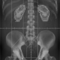
Most modern radiation therapy of cancer involves noninvasive targeting of localized disease and conformal avoidance of nontarget tissues. Radiation dose is delivered to the volume of intended treatment without the benefit of physically seeing the regions being irradiated. Therefore, imaging guidance is crucial in every step of the radiation therapy, including cancer diagnosis, staging, and delineation; treatment simulation and planning; patient setup, tumor localization and motion monitoring; and treatment response assessment, efficacy evaluation and strategy refinement. In fact, most of the significant advances in radiation oncology over the last three decades have been made possible by preceding advances in medical imaging, including computed tomography (CT), magnetic resonance imaging (MRI), magnetic resonance spectroscopic imaging (MRSI), positron emission tomography (PET), single photon emission computed tomography (SPECT), and ultrasound (US). With the aid of CT and MRI, three-dimensional (3D) shapes of treatment regions and critical normal structures are delineated with great precision, thus reducing the chance for marginal misses of the tumor and minimizing the exposure of normal tissues to high radiation dose. MRI, MRSI, PET, and SPECT images provide additional functional and biological information to define and delineate the extent of the disease. Examples of image guidance in various stages of radiation therapy are illustrated in Figure 14.1.
Image-guided radiation therapy (IGRT) is composed of a multitude of major innovations to address some of the problems arising from inter- and intra-fractional anatomic variations. IGRT aims to deliver a radiation treatment as it is planned based on an image acquired at simulated treatment conditions. This simulation image establishes a reference of 3D patient anatomy (with possible inclusion of tumor respiratory motion information) for both image-based treatment planning and image-guided treatment delivery. The former follows the exact 3D anatomy (both the tumor and normal tissues) for dosimetric planning, while the latter focuses mostly on tumor alignment between the reference image and daily images at the treatment unit prior to and during treatment, in reference to the treatment beams. Therefore, the variations of tumor position in the image-guided inter-fractional setup (i.e., variation between treatment fractions) and intra-fractional organ motion (i.e., motion occurring within a treatment fraction) could be corrected for more accurate delivery of the planned treatment dose to the target. As the variation of normal tissues is usually ignored in the current image-guided approach, dosimetric and clinical consequences must be assessed.
Increasing evidence shows that there are substantial inter- and intra-fractional variations in the shapes, volumes, and positions of treatment targets and the intervening and surrounding normal tissues, in contrast to the “snapshot” planning anatomy of a patient. The causes of such variations include body shift, rotation and deformation, respiration-induced organ motion, weight loss, and radiation-induced changes such as tumor shrinkage. These variations could have a significant impact on the outcome of treatments, as they may result in underdosing the target or overdosing the organs at risk (1,2,3). In the current state of the art of the planning and delivery of radiation therapy, based on the use of CT, PET, and MRI images acquired prior to the course of treatments, it is assumed implicitly that patient’s anatomy discerned from initial imaging remains static throughout the course of the radiation therapy. In the current practice, wide treatment margins, derived from population-based studies, are used to ensure coverage of the disease, exposing considerable volumes of normal tissues to unwanted radiation. The use of large margins limits the ability to safely deliver higher tumor doses because of increased risk of normal tissue toxicity, especially for hypo-fractioned stereotactic body radiotherapy (SBRT), in which the high dose per fraction exceeds the normal tissue’s capacity for sublethal repair. Furthermore, the margin needed for some patients exhibiting large target variations may exceed the population-based margin, potentially leading to marginal misses, especially with the use of highly conformal modalities, such as 3D conformal radiotherapy (3DCRT), intensity-modulated radiotherapy (IMRT), volumetric-modulated arc therapy (VMAT), and proton therapy (4,5,6). Treatment planning and delivery techniques that do not correct for such daily volumetric variations adequately may lead to suboptimal treatments. These factors may, in part, be responsible for the poor outcome and high toxicity in radiation therapy for some cancers. IGRT has the potential to target gross and microscopic diseases accurately, to
individualize treatments to reduce margins, and to allow radiation dose escalation to higher levels with the expectation of improving local control and reducing toxicity (7,8). Although this rationale is supported by increasing evidences, continuing research to further develop IGRT methods for clinical trials is required to determine the true clinical promise of IGRT.
individualize treatments to reduce margins, and to allow radiation dose escalation to higher levels with the expectation of improving local control and reducing toxicity (7,8). Although this rationale is supported by increasing evidences, continuing research to further develop IGRT methods for clinical trials is required to determine the true clinical promise of IGRT.
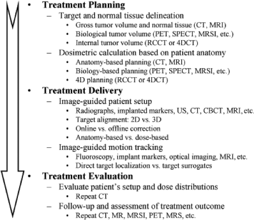 Figure 14.1. Image guidance at various stages of the radiotherapy process. |
This chapter focuses on IGRT technologies related to treatment planning as well as treatment delivery. The related topics are covered in the following sections: second and third sections introduce various forms of IGRT technologies and their commercial implementations for inter-fractional and intra-fractional imaging, respectively. Fourth section reviews requirements and considerations for IGRT, including quality assurance (QA). Various possible IGRT strategies, margin assessment and reduction, and clinical implications are described in fifth section. Finally, sixth section attempts to look into the future and speculate on new processes coming into this field.
Inter-Fractional IGRT Imaging Modalities
In this section, we focus on in-room IGRT imaging modalities for daily patient setup. Images acquired immediately prior to treatment are used to reposition the patient so as to align the target or its surrogate (such as implanted radio-opaque fiducial markers in or near the tumor) with the planned radiation beams. This is the simplest form of image-guided radiotherapy without modification of the original treatment design. A couch positional adjustment is typically used to realign the patient. The inter-fractional imaging modalities may be classified as follows.
2D Radiographic Imaging
Two-dimensional (2D) radiographic (projection) imaging is typically used in treatment rooms to align the patient relative to the radiation beams. Megavoltage (MV) electronic portal imaging (EPI) is the most commonly used form of radiographic imaging (9,10). MV imaging uses therapy x-ray beams and an amorphous-silicon (a-Si) flat-panel imager to verify patient’s setup, defined as the position of the skeletal anatomy. Other uses of MV imaging are to verify treatment beam apertures prior to treatment (11,12) and in vivo dosimetry during treatment (13). Because the same therapy MV x-ray beam is used for verification, it provides direct in-field verification of treatment delivery, and therefore serves as a “gold standard” for validating new IGRT techniques. Disadvantages of MV imaging include higher radiation dose to the patient from the procedure (typically 1–5 cGy) and poorer image quality due to a large Compton scattering contribution from the higher x-ray energies. Recently, in-line low-energy (∼4 MV), with a low atomic number (Z) target (e.g., carbon) without beam flattening filter, has become available, which produces portal images of improved soft-tissue contrast with lower imaging dose (14).
Two general categories of 2D kilovoltage (kV) x-ray imaging are frequently used for IGRT. One is a gantry-mounted kV imaging system on a linear accelerator (linac) that is orthogonal to the therapy MV x-ray beam. The x-ray source and flat-panel imager are mounted on retractable arms. Kilovoltage x-ray imaging provides near-diagnostic quality images. With either kV or MV imaging, determination of the correction to patient position commonly uses orthogonal image pairs that are matched to digitally reconstructed radiographs (DRRs) derived from the planning CT as a reference. The second category of kV imaging is ceiling-mounted systems (15). These systems provide an oblique orthogonal image pair for stereoscopic imaging at a wide range of treatment couch angles. Most kV x-ray radiographic imaging systems have a companion fluoroscopic imaging mode, which is useful for observing motion of the internal anatomy or implanted fiducial markers.
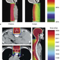
Kilovoltage radiographs are often not sufficient for detecting soft-tissue targets but are more successful in aligning skeletal landmarks or implanted radio-opaque fiducials as target surrogates. In-room kV x-ray imaging represents a major improvement over MV imaging due to its superior image quality and its low imaging dose. The different appearance of kV and MV images, as shown in Figure 14.2 (thorax), results from the higher proportion of Compton scattering and high-energy electrons in MV x-ray beams relative to kV x-rays.
As the kV imaging beam lines are not aligned with MV beam line, the kV-MV isocenter discrepancy must be established within a clinical tolerance through initial and periodic QA processes. The radiation dose from kV imaging is low, typically in the range of 0.01 to 0.1 cGy per
image, which facilitates its use for daily image-guided patient setup.
image, which facilitates its use for daily image-guided patient setup.
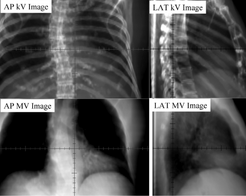 Figure 14.2. The appearance of anatomy kV (top row) and MV (bottom row) radiographs can be quite different. At kV x-ray energies, the bony structures are enhanced; at the therapeutic (MV) energies, the air cavity is enhanced. Direct comparison of kV DRRs with MV portal images can be difficult. |
3D Tomographic Imaging
CT imaging inside the treatment room provides 3D anatomical information and improved soft-tissue visibility, thus providing advantages over radiographic imaging. In-room CT images may potentially be used to reconstruct dose distributions based on anatomy captured at treatment; its application to adaptive radiation therapy, in which a patient’s treatment plan is modified in response to changes in anatomy, is an active area of investigation. In the following sections, we describe various forms of in-room CT-based on x-ray systems.
kV Helical CT
Helical single- or multiple-slice CT systems have been widely used in diagnostic imaging and radiation treatment planning for many years. The first integrated clinical system, which combined a linac unit and conventional CT unit in the same room was developed by Uematsu et al. at the National Defense Medical College, Saitama, Japan (16). The system was designed for noninvasive, frameless stereotactic radiotherapy of brain and lung cancers, to reduce the uncertainty in multi-fractional frame-based stereotactic radiotherapy. A combination of single-slice Philips CT scanner and Varian Clinac 2100EX, which used a rail system to transport the patient between treatment and CT couches, was assembled at the Memorial Sloan-Kettering Cancer Center. The system was used for treatment of paraspinal lesions and prostate cancer (17,18).
The first commercial CT-linac system in the United States was installed in 2000 in Morristown Memorial Hospital, New Jersey (19). The system consists of a Siemens medical linac and a moveable Siemens CT scanner that slides along a pair of rails (“CT-on-Rails”). A picture of the system is shown in Figure 14.3A. The CT scan is performed with the patient rotated 180 degrees from the treatment position. The initial clinical experience with this system has been reported by Wong et al. and Fung et al. (19,20). A similar “CT-on-Rails” commercial system is installed at the University of Texas M. D. Anderson Cancer Center (EXaCT™, Varian Oncology Systems, Palo Alto, CA). The mechanical accuracy of the system is found to be within 0.5 mm (21). The system, as shown in Figure 14.3B, has been recently upgraded with a 6-degree-of-freedom couch (HexaPOD™, Medical Intelligence, Germany),
which allows for more precise couch translations and small rotations. The system has been routinely used for fractionated SBRT, treatment of spinal metastases (22), and lung cancers. The biggest advantage of an in-room CT scanner for IGRT is the similarity of the image quality and fields of view with planning CT images.
which allows for more precise couch translations and small rotations. The system has been routinely used for fractionated SBRT, treatment of spinal metastases (22), and lung cancers. The biggest advantage of an in-room CT scanner for IGRT is the similarity of the image quality and fields of view with planning CT images.
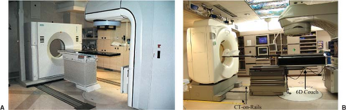 Figure 14.3. A: A Siemens Primatom™ CT-on-rails contains a Primus™ linear accelerator and a Somatom™ sliding-gantry CT scanner. The first Primatom™ was installed at the Morristown Memorial Hospital, New Jersey (Photograph courtesy of Lisa Grimm, PhD). B: A CT-on-rails system combining a General Electric Smart Gantry™ CT scanner and a Varian 2100EX linear accelerator. A 6-degree-of-freedom couch (HexaPOD™, Medical Intelligence, Germany) is installed on top of the standard Varian ExaCT™ couch. CT scan of the patient in immobilized treatment position is acquired after rotating the couch 180 degrees. |
kV Cone-Beam CT
Gantry-mounted kV imaging systems are capable of radiography, fluoroscopy, and cone-beam CT (CBCT), providing a versatile solution for IGRT applications (23,24,25). CBCT imaging involves acquisition of projection images of the patient as the gantry rotates through an arc of at least 180 degrees plus the “cone-beam angle” subtended by the imaging panel (∼200 degrees total). A filtered back-projection algorithm is used to reconstruct the volumetric images (26). Geometric calibration of the CBCT system is needed periodically to maintain image quality and geometric accuracy (27). Corrections on the order of 0.2 cm are required to compensate for the gravity-induced flex in the support arms of the source, detector, and gantry. Sub-millimeter spatial resolution has been demonstrated in phantom. It is possible to reconstruct volumetric images with nearly isotropic spatial resolution, which is useful in cases requiring high resolution, such as stereotactic radiosurgery. Kilovoltage CBCT images demonstrate acceptable soft-tissue contrast for target and organ-at-risk localization.
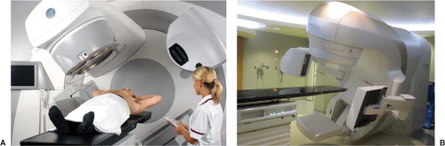 Figure 14.4. A: An Elekta Synergy™ unit (Elekta Inc., Sweden). B: A Varian TrueBeam™ unit (Varian Oncology Systems, Palo Alto, CA) (Photograph courtesy of Yingli Yang, PhD). Both linear accelerators have a kV imaging system orthogonal to the therapy beam direction. Both systems provide 2D radiographic, fluoroscopic, and CBCT modes. |
Since October 2005, all three major manufacturers have offered CBCT capabilities (Elekta Synergy™, Elekta Inc., Sweden; Varian On-board Imager (OBI), Palo Alto, CA; and Siemens Artiste™, Germany). A picture of the commercial implementation of the kV-CBCT system by Elekta (Synergy™) and by Varian (TrueBeam™) is shown in Figure 14.4A and B, respectively. Elekta’s system uses a
slightly larger flat panel detector (41 by 41 cm), compared to Varian’s detector (40 cm wide by 30 cm long), which limits the scan length to 15 cm when using the full-fan scanning mode. A “shifted detector” (or half-fan) technique can extend the axial field of view (FOV) to at least 40 cm (28). To further increase the FOV with the existing imager size, Li et al. has recently proposed an “off-axis” ellipse cone-beam scanning method, which shifts the center of rotation during CBCT to increase the sampling outside regular FOV, while sacrificing the sampling in the center (29).
slightly larger flat panel detector (41 by 41 cm), compared to Varian’s detector (40 cm wide by 30 cm long), which limits the scan length to 15 cm when using the full-fan scanning mode. A “shifted detector” (or half-fan) technique can extend the axial field of view (FOV) to at least 40 cm (28). To further increase the FOV with the existing imager size, Li et al. has recently proposed an “off-axis” ellipse cone-beam scanning method, which shifts the center of rotation during CBCT to increase the sampling outside regular FOV, while sacrificing the sampling in the center (29).
Limitations of CBCT image quality include elevated x-ray scatter, which reduces image contrast and introduces cupping artifacts. Scatter can be reduced by using post-processing methods (Elekta’s solution) (30) or anti-scatter grids (Varian’s solution). Because of regulations on gantry rotation speed (maximum 1 rpm), CBCT image quality is adversely affected by the breathing motion. The IGRT setup process may add 5 minutes (1–2 min scan time and 1–3 min for image registration and approval) to the regular treatment schedule.
MV Helical CT (Tomotherapy)
Tomotherapy (TomoTherapy Inc., Madison, WI) is an integrated technology that combines a helical megavoltage CT (MVCT) with a linear accelerator, which is specially designed for delivering intensity-modulated radiation in a slit geometry. The concept was originally proposed by Mackie et al. (31,32) and substantially developed by the University of Wisconsin group (33,34,35,36,37). Helical tomotherapy refers to the continuous gantry and couch motion, which, as shown in Figure 14.5A, resembles the motion from a conventional helical CT scanner. Low-dose, typically 1 to 2 cGy, pretreatment MVCT images are obtained from the same treatment beam line but with a nominal energy of 4 MV. The CT detector uses an array of 738 channel xenon ion chambers and an FOV of 40 cm can be reconstructed. There is no limitation in the superior–inferior direction.
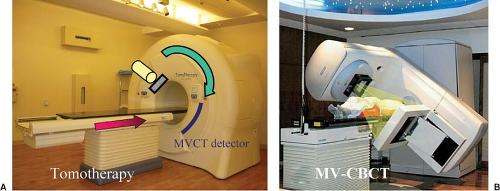 Figure 14.5. A: A picture of tomotherapy unit (TomoTherapy Inc., Madison, WI) (Photograph courtesy of H. Ning, PhD). Tomotherapy is an integrated IGRT system, which combines a linear accelerator with an MVCT image guidance system. B: A Siemens MV CBCT imaging system using a conventional linac and a flat-panel EPID. Source: Reprinted from Morin O, Gillis A, Chen J, et al. Megavoltage cone-beam CT: system description and clinical applications. Med Dosim 2006;31:51–61. |
Owing to the use of MV beam for imaging, MVCT image quality is not as high as that from a diagnostic CT image: the noise level is higher and low-contrast resolution is less. Nevertheless, the MVCT images provide sufficient contrast to verify patient position (37) and to delineate many anatomic structures (38,39). It is interesting to note that the MVCT numbers are linear with respect to the electron density of material imaged, which yields reliable and accurate dose calculations (40). This capability, together with the strong research effort in treatment plan optimization and image registration by the TomoTherapy group (41,42,43), makes tomotherapy appealing as an integrated solution for image-guided adaptive radiotherapy.
MV Cone-Beam CT
Megavoltage cone-beam CT (MV CBCT) uses the electronic portal imaging device (EPID) mounted on a linac gantry and the therapy MV x-ray as a basic configuration for CT imaging. The initial attempt was performed by Swindell et al. (44) and subsequently implemented by Mosleh-Shirazi et al. (45). With recent advance in highly sensitive EPIDs, particularly a-Si flat panel detectors (46,47,48), it has become possible to rapidly acquire multiple, low-dose 2D projection images with current treatment machines. Similar to kV CBCT described in previous sections, a CBCT imaging system uses a large image detector and a single rotation of the x-ray source to complete the image acquisition. In addition to the MV x-ray source, the use of a large-area receptor (EPID) with no effective MV scatter-reduction mechanism limits image quality. The amount of scatter reaching the detector depends on the
photon energy, field size, and the thickness of the imaged object; however, the imaging system can be optimized by calibrating the system using standard site-specific calibration phantoms (49,50).
photon energy, field size, and the thickness of the imaged object; however, the imaging system can be optimized by calibrating the system using standard site-specific calibration phantoms (49,50).
Figure 14.5B shows a prototype MV CBCT system from Siemens. The system consists of a standard treatment unit (Primus™, Siemens Medical Solutions, Concord, CA) and an a-Si flat-panel adapted for MV photons on a retractable support. The 41 × 41 cm flat-panel x-ray detector (AG9-ES, PerkinElmer, Optoelectronics) consists of a 1 mm copper plate and a Kodak Lanex fast scintillation plate (Gd2O2S:Tb) overlaid on a light-sensitive and charge-integrating thin-film transistor (TFT) array. Due to a more stringent requirement for geometric integrity, a calibration procedure is required to correct for mechanical support sag (49,50). The image acquisition lasts ∼45 seconds with gantry rotation over a 200-degrees arc, at a rate of one image per degree. Image reconstruction time is less than 2 minutes for a 256 × 256 × 270 image volume (0.7 mm3 voxel size). Imaging dose ranges from 2 to 8 cGy (51).
The MV CBCT system has good image quality for bony structures and acceptable quality for soft-tissue targets, due to the higher imaging dose. An advantage of both MV CBCT and MVCT systems is the reduced influence of implanted metal objects on image quality, in contrast to kV CT, which exhibits strong artifacts when high-Z material is present. MVCT images thus provide complementary information, which cannot be discerned in conventional CT images (Fig. 14.6). An additional advantage of MV CBCT is that the physics of absorbed dose from a therapeutic MV beam is well understood, thus enabling accurate calculation of dose from an MV CBCT scan that could be included in the treatment plan (51). Soft-tissue contrast is the principal limiting factor of MV CBCT systems. Investigators at the University of California San Francisco have used a lower-Z target material, which generates more low-energy photons and enhances image contrast (49). One study showed that removal of the flattening filter improved contrast by 200% (14).
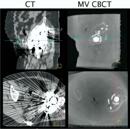 Figure 14.6. Images showing the artifacts due to the presence of metal objects in the conventional kV CT images (left panels). Artifact-free images were obtained with a MV CBCT (right panels). Source: Reprinted from Morin O, Gillis A, Chen J, et al. Megavoltage cone-beam CT: system description and clinical applications. Med Dosim 2006; 31:51–61. |
Digital Tomosynthesis
Digital tomosynthesis (DTS) is a special situation of tomographic reconstruction, which uses limited arc (20 to 40 degrees) of projection images (53,54,55). The reconstruction planes are approximately perpendicular to the direction of the x-ray beam at the arc center. They do not have to go through the isocenter, but can be at different depths in the patient. In some methods, reconstruction is followed by a procedure to suppress out-of-plane objects (56,57). The principal advantage of DTS over CBCT is the shorter scan time, which is typically less than 10 seconds. DTS provides soft-tissue image visualization, which can be improved in respiratory disease sites by combining with breath-hold or respiration correlation of the projection images (58).
Depending on the acquisition arc length, spatial resolution is less in the direction perpendicular to the reconstructed planes, which can be addressed by acquisition of a second DTS from a quasi-orthogonal direction to the first. Reference DTS images can be calculated from the planning CT, similar to the calculation of DRRs (59). A comparison of the conventional CT, CBCT, and DTS images of the same patient is shown in Figure 14.7.
Hybrid Cone-Beam CT
Combining kV and MV projection images for CBCT reconstruction has been reported (60). A hybrid CBCT can be achieved by combining orthogonal kV and MV x-ray projection images with a partial arc gantry rotation as little as 90 degrees (61). The resultant projection images span an arc length of 180 degrees. Acquisition requires only 15 seconds, making it optimal for breath-hold imaging.
4D Computed Tomography Imaging
Respiratory motion is one of the important factors in the management of radiation therapy for moving tumors, which can have displacements up to 3 to 4 cm (62). CT scans acquired synchronously with the respiratory signal can be used to reconstruct a set of (3D) CT scans, representing the 3D anatomy at different times (or respiratory phases). This collection of 3D CT data sets is called respiration-correlated CT (RCCT), or 4D CT, which describes the snapshots of patient’s 3D anatomy over a periodic respiratory signal. Typically, the breathing cycle is divided
into 10 respiratory phases. Four-dimensional medical imaging techniques has been reviewed recently (63).
into 10 respiratory phases. Four-dimensional medical imaging techniques has been reviewed recently (63).
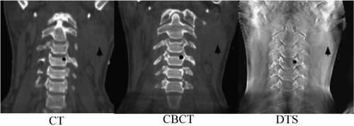 Figure 14.7. A coronal planar image reconstruction based on conventional kV CT (left), CBCT (middle), and digital tomosynthesis (DTS, right) (Photograph courtesy of Fang-Fang Yin, PhD). |
Respiration-Correlated CT
The approach common to RCCT methods is to acquire sufficient data for generating CT images at all phases of the respiratory cycle while simultaneously recording respiration, then retrospectively correlating the CT projection images with phase. CT acquisition uses either a cine or helical mode. In cine mode, repeat CT projections are acquired over slightly more than one respiratory cycle with the couch stationary while recording patient respiration; the couch is then incremented and the process repeated. Following acquisition, the images are sorted with respect to the respiratory signal, leading to a set of volume images at different respiration points in the cycle (64,65). Helical acquisition uses a low pitch and adjusting the gantry rotation period such that all voxels are viewed by the CT detectors for at least one respiratory cycle (66,67). RCCT images have been widely characterized and applied clinically for estimating the extent of a moving tumor in lung (68,69,70).
The selection of the type of respiratory signal can vary, which may change the interpretation of the RCCT images; however, a periodic motion is always implied. Deviations from the regular periodic motion will have an impact on the quality of RCCT images and on the accuracy of anatomy discerned from these images. Commercial systems commonly use one of the two types of respiratory monitors. One such monitor (Real-time Position Management, RPM™, Varian Oncology Systems, Palo Alto, CA) captures the up/down motion of a box with infrared reflectors placed on the patient’s abdomen or chest using an infrared camera. The other is a “pneumo bellows” system (Phillips Medical Systems, Milpitas, CA) that records the digital voltage signal from a differential pressure sensor wrapped around the patient’s abdomen. RCCT scans can be used in so-called 4D treatment planning to explicitly account for tumor motion (63,68,70,72,73).
CT images are sorted based on a respiration phase angle assigned by an algorithm that determines the periodic behavior of the respiratory signal. Phase-based sorting assumes repeatable breathing cycles, that is, that the anatomy is at same position for a given phase in every cycle, which is usually not the case for normal breathing with its varying cycle-to-cycle amplitude variations, and has led to investigations into sorting based on the displacement of the respiratory signal (71,74,75,76).
Respiration-Correlated CBCT
A limitation of CBCT systems is image degradation caused by patient motion artifacts, which is a consequence of the limited gantry speed and the resultant long (∼1 min) acquisition times. Respiratory motion in particular degrades images in the thorax and abdomen. Different methods are under active investigation to reduce motion in CBCT. One approach is respiration-correlated CBCT (RC-CBCT) using retrospective sorting of projection images into different breathing phases (77,78). A slower gantry rotation is required to acquire sufficient projections in each phase bin, resulting in scan times of 3 to 6 minutes. The limited number of projections per phase reduces the contrast resolution and introduces image view artifacts; thus, the method is more suited to detecting high-contrast objects such as tumor in parenchymal lung (77,78,79).
Non-radiographic Imaging
Ultrasound Imaging
Ultrasound is a noninvasive, non-radiographic, and real-time imaging technique for soft-tissue targeting in radiotherapy,
particularly for prostate cancer, but also for upper abdominal malignancies (85,86,87,88,89). Fung et al. have recently reviewed ultrasound guidance for IMRT (90).
particularly for prostate cancer, but also for upper abdominal malignancies (85,86,87,88,89). Fung et al. have recently reviewed ultrasound guidance for IMRT (90).
The ultrasound transducer, which is made of the piezoelectric crystal, is both a sound source and a sound detector. The ultrasound transducer transmits brief pulses of ultrasound that propagate into the tissues. Whenever there is a change in acoustic impedance, for example, owing to the tissue density or elasticity changes at the interface of two organs, some of the ultrasound will be reflected back to the transducer as echoes. The round-trip time from the pulse transmission to reception of an echo is used to determine the transducer-to-object distances. A scan line converter will construct a 2D image of the patient, in which the amplitude of echoes varies along depth direction. When sweeping the ultrasound through a volume, a 3D ultrasound image can be constructed. The basic principles of this imaging technique limit its use to soft-tissue structures and tumors in pelvic, abdominal, and breast locations.
Although ultrasound has been widely used in patient setup, inherently poor image quality and the unfamiliar appearance of ultrasound images for radiation therapists have limited its potential for more precise image guidance. Figure 14.8 shows a pair of ultrasound images (top row) and corresponding CT images (bottom row) for a prostate cancer patient undergoing ultrasound-guided setup (91). In this example, the agreement between ultrasound and CT alignments is within 2 mm. It has been shown that the inter- and intra-user variability is large for ultrasound-guided setup, mainly because of the poor image quality, anatomic distortion due to pressure variation and inadequate user training (86,92). When compared with implanted fiducial markers for prostate localization, the ultrasound alignment displayed even more variations (93) and a larger planning margin is recommended (94). Dobler et al. studied the displacement of prostate when acquiring transabdominal ultrasound images (95). X-ray simulations were performed before and during ultrasound image acquisition for 10 patients who had undergone iodine-125 seed implantation. The seeds, which were visible in x-ray images, were used to represent prostate position. A maximum displacement of the prostate of 2.3 mm in anteroposterior and 1.9 mm in craniocaudal direction and a rotational change of up to 2.5 degrees were observed. If the system was not handled correctly and too much pressure was applied, a shift of the prostate of up to 10 mm could be induced. Tome et al. has reported on ultrasound commissioning and QA procedure for radiation therapy (96).
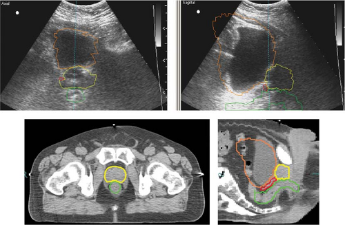 Figure 14.8. A pair of ultrasound images is shown in the top row. The images were acquired from an ultrasound-guided alignment system (BAT™, NOMOS, Chatsworth, CA). A pair of CT images of the same patient is shown in the bottom row. The CT images were acquired using an in-room CT-on-rails scanner within 5 minutes of the ultrasound image acquisition. The alignment relative to the planning CT by these two independent systems was within 2 mm. |
Stereoscopic Optical Surface Imaging
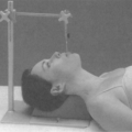
Stereoscopic optical surface imaging (OSI) provides real-time imaging capability, primarily used in patient setup for superficial tumors, such as the breasts, or immobile tumors such as in the head. One currently available OSI device (AlignRT™, VisionRT, Ltd., London, UK) is composed of two to three ceiling-mounted stereo-camera pods, each contains two cameras and a speckle pattern projector. The triangulation between the fixed stereo cameras and a skin point identified by the speckle pattern serves to calculate their distances and the location of the point in space. A patient skin surface image is reconstructed from the visible surface points. The accuracy of the surface imaging is within 1.0 mm.
Because OSI does not visualize the tumor, it requires substantial validation against another established image modality, such as radiographic imaging. Early studies of surface imaging in radiotherapy have been reported by Massachusetts General Hospital (97) and Johns Hopkins University (98) in 2005. Validated with x-ray imaging, OSI provides a quick and non-radiologic means for image-guided setup. It has been applied in breast, lung, brain, and head and neck. The common procedure for patient setup is to register the surface image to a reference region of interest (ROI) defined on the delineated patient surface in a simulation CT.
Magnetic Resonance Imaging
MRI is based on the radiofrequency signal from the relaxation process of the dipole moment of an atom with unpaired proton, such as 1H in tissue, after it is excited with a radiofrequency pulse sequence in the presence of an external magnetic field. The field strength is ∼0.2 Tesla (T) for open-field MRI and 1.5 T or 3 T for a regular MRI scanner. The geometric location of the signal is determined using the field gradient, phase and frequency encoding. The soft-tissue heterogeneity provides an environment that alters the relaxation process, thus providing high soft-tissue contrast.
MRI imaging is more versatile than radiologic imaging, as it provides different image appearances when different pulse sequences are applied, such as T1-weighted, T2-weighted, and fast fluid-attenuation inversion recovery (FLAIR) (99). These MRI images are often used in delineating a tumor or postoperation cavity and evaluating local edema, especially for brain cancer. MRI can also produce non-axial scans in any spatial orientation. Like radiologic imaging, MRI can produce 2D planar, 3D volumetric, and 4D volumetric set images (63). Four-dimensional prospective volumetric MRI imaging has been utilized in radiotherapy (100).
MRI may suffer from geometric distortion due to nonuniformity of the external magnetic field strength. This scanner-specific factor can be corrected by measuring the field gradient with a large grid phantom (101). MRI does not produce a visible image in bone due to little relaxation in the solid phase. A limitation for radiotherapy applications is that an MR image cannot be easily converted to electron density, which is essential for dosimetry calculation in a treatment planning system. Recently, MRI-based treatment planning has been reported (102,103,104).
Several MRI-guided radiotherapy systems are currently under development. Such systems offer not only in-room soft-tissue-based target alignment, but also near real-time MRI volumetric imaging for tumor motion monitoring. The section “MRI Real-Time Volumetric Imaging” discusses these systems in more detail.
Intra-Fractional Real-Time Imaging and Motion Compensation
The main goal of real-time tracking is to minimize the effect of target motion not only between treatments, but also during a treatment fraction. Real-time tracking usually requires real-time motion monitoring (detection) and the execution of correction with the shortest time delay. In almost all cases, implanted markers are used as surrogates for target position. Therefore, the proximity of the markers to the target and their motion relative to the target are important factors in their reliability for a real-time tracking system. In the following sections, we review different approaches for real-time monitoring and tracking.
Fluoroscopic Imaging with Implant Fiducials
Commercial fluoroscopy-based tracking systems can be categorized into room-mounted and linac gantry-mounted systems. The primary reason for using fluoroscopic imaging is to detect metal fiducials, which are implanted in or near the tumor. The fluoroscopic images can be matched to a reference DRR.
A very interesting, room-mounted system for real-time tracking has been developed by Shirato et al. in collaboration with Mitsubishi at the University of Hokkaido (105,106). It uses a pair of x-ray tubes that rotate on a circular track embedded in the floor, as shown in Figure 14.9A. Each tube has a corresponding x-ray detector that rotates synchronously on a ceiling-mounted track, so as to avoid obstruction of the patient by the treatment gantry. The x-ray tubes allow pulsed imaging interlaced with linac pulses to treat the patient. The radio-opaque marker images are tracked with pulsed fluoroscopy prior to the beginning of the treatment and patient is repositioned so that the end of one of the tracks corresponding to the least mobile portion of the motion is within a predefined gating window. During irradiation, fluoroscopy continues and the beam is automatically switched on when the detected image of the fiducial is within the window; otherwise, it is turned off.
A commercially available room-mounted system, as shown in Figure 14.9B, is developed by BrainLab (ExacTrac® BrainLAB AG, Feldkirchen, Germany). The ExacTrac is an
integrated IGRT system for target localization, setup correction, and the delivery of high-precision stereotactic radiotherapy and stereotactic radiosurgery. The image guidance utilizes two distinct imaging subsystems: a real-time infrared (IR) tracking and a kV stereoscopic x-ray imaging subsystem. Two ceiling-mounted IR cameras are used to monitor the movement of infrared-reflecting markers placed on patient’s skin or on the reference frame mounted on the treatment couch. The marker images are automatically compared to a stored reference, generating initial couch shift instruction to set up the patient. The x-ray imaging system performs further internal target alignment based on either bony landmarks or implanted fiducial markers. The reference DRRs are provided by the BrainLab treatment planning system. During treatment delivery, the IR tracking system and the fluoroscopic x-ray imaging system work together to monitor target position and to perform treatment interventions. The external fiducial markers can be “tuned” to the internal fiducial markers during a pretreatment verification procedure. Two types of treatment interventions can be performed: adaptive gating of the treatment beam or real-time correction of target offset by using a 6D robotic couch (ExacTrac®, BrainLAB AG, Feldkirchen, Germany). CyberKnife™ system (Accuray Inc., Sunnyvale, CA) has also its own room-mounted stereoscopic x-ray imaging system and 6D robotic couch. Research and clinical experience of using these systems have been reported by various groups (107,108,109,110).
integrated IGRT system for target localization, setup correction, and the delivery of high-precision stereotactic radiotherapy and stereotactic radiosurgery. The image guidance utilizes two distinct imaging subsystems: a real-time infrared (IR) tracking and a kV stereoscopic x-ray imaging subsystem. Two ceiling-mounted IR cameras are used to monitor the movement of infrared-reflecting markers placed on patient’s skin or on the reference frame mounted on the treatment couch. The marker images are automatically compared to a stored reference, generating initial couch shift instruction to set up the patient. The x-ray imaging system performs further internal target alignment based on either bony landmarks or implanted fiducial markers. The reference DRRs are provided by the BrainLab treatment planning system. During treatment delivery, the IR tracking system and the fluoroscopic x-ray imaging system work together to monitor target position and to perform treatment interventions. The external fiducial markers can be “tuned” to the internal fiducial markers during a pretreatment verification procedure. Two types of treatment interventions can be performed: adaptive gating of the treatment beam or real-time correction of target offset by using a 6D robotic couch (ExacTrac®, BrainLAB AG, Feldkirchen, Germany). CyberKnife™ system (Accuray Inc., Sunnyvale, CA) has also its own room-mounted stereoscopic x-ray imaging system and 6D robotic couch. Research and clinical experience of using these systems have been reported by various groups (107,108,109,110).
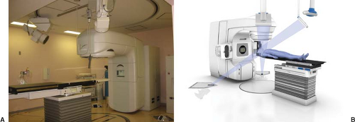 Figure 14.9. Two room-mounted kV image-guided IGRT real-time tracking systems. A: A real-time tracking radiation therapy (RTRT) system (Photograph courtesy of Hiroki Shirato, MD, PhD). B: ExacTrac system, BrainLAB AG, Feldkirchen, Germany (Photograph courtesy of BrainLAB AG.) |
Gantry-mounted kV imaging systems usually have only one kV x-ray imager and achieve the orthogonal pair by rotating the gantry. These systems include Varian’s On-board Imager (OBI) and Elekta’s Synergy. These kV imaging beam lines are orthogonal to the MV treatment beam line (EPID), sharing the same isocenter of gantry rotation, as shown in Figure 14.4. The gantry-mounted kV imaging system is not blocked by the treatment unit, but it may have limited clearance or the potential for collision with the immobilization device or the couch. The kV-MV configuration provides a possibility to acquire images during treatment (111). To avoid scatter interference between the two x-ray beams, alternating the beam-on time may be used (112).
A prototype kV-MV dual in-line imaging system is commercially available (Artiste™, Siemens Medical Systems, Germany) (113,114). This is achieved by placing the kV x-ray tube in a retractable lower shelf. The kV image detector is mounted just below the MV collimator. The MV therapy beam must penetrate the kV image detector to treat the patient. This design allows for simultaneous imaging of the beam shaping device (MLC-collimated beams) and patient’s anatomy for beam-by-beam verification of treatment delivery or motion compensation.
Optical Fiducial Motion Surrogates
Optical tracking determines an object’s position by measuring light either emitted or reflected from the object. The hallmark of optical tracking systems is their high spatial and temporal resolutions (0.1 mm and <0.1 s, respectively) in tracking infrared markers attached to the patient’s external surface. The positions of the optical markers relative to the target volume, together with the desired marker positions relative to the treatment isocenter, are determined during CT simulation. In the treatment room, the real marker positions are measured relative to isocenter; a rigid-body transformation determines marker displacements from their desired positions and hence target displacement from the isocenter. Real-time feedback allows one to correct the patient’s position continuously during treatment. Meeks et al. have reviewed the technology in several implementations for intracranial and extracranial stereotaxis radiotherapy (115). The first systems used rigid arrays of optical markers that were attached to the patient via a biteplate linkage. Subsequent
systems for extracranial radiotherapy tracked external markers to determine the patient position and/or gate the radiation beam based on patient motion.
systems for extracranial radiotherapy tracked external markers to determine the patient position and/or gate the radiation beam based on patient motion.
Video-Based 3D Optical Surface Imaging
Real-time 3D-surface matching has been characterized for clinical use (97,98,116). The reference surface image is either a 3D optical surface image acquired at simulation or a CT/MRI-surface rendering from the treatment plan. The real-time 3D surface images are captured by stereoscopic video cameras mounted on the ceiling of the treatment vault. A fast automatic alignment between the real-time surface and the reference surface using a modified iterative-closest-point method leads to an efficient and robust surface-guided target refixation. Experimental and clinical results demonstrate the excellent efficacy of <2 minutes set-up time and high accuracy and precision of <1 mm in isocenter shifts and <1 degree in rotation (116).
The AlignRT system has been described in a previous section for patient alignment. In addition, it offers capabilities for real-time motion monitoring. Due to processing time required for image reconstruction, it only provides prospective imaging at one to five frames per second (fps), far below its maximum capture rate (∼15 fps), (117) depending upon the size and resolution of ROI. Several investigators have shown that this real-time surface imaging capability can be applied to head motion monitoring during frameless stereotactic radiotherapy or radiosurgery (52,118,119). Using a 3D optical surface image acquired at treatment as reference, systematic errors of the imaging system can be cancelled out and achieve a sub-millimeter accuracy for motion detection (52).
Real-Time Electromagnetic Localization and Tracking
Continuous tracking of target position without ionizing radiation is possible with a novel technology utilizing AC electromagnetic fields to induce and detect signals from implanted “wireless” transponder (Calypso Medical Technologies, Inc., Seattle, WA). The system consists of a console, optical tracking system, and a tracking station. The console instrument is situated in the treatment room and includes a display screen and the AC magnetic array (Fig. 14.10). The magnetic array is lightweight and contains source coils that generate signals to excite the transponders, and sensor coils that detect the unique response signals returned by each transponder. Unlike passive fiducial markers, the Calypso system can actively detect the position of transponders without using the radiographic method. The Calypso 4D Localization System can update target position 10 times per second, which is sufficiently fast to track breathing motion of the tumor. Sub-millimeter tracking accuracy and clinical experience in prostate target localization has been reported (120,121,122,123,124).
Related posts:

Stay updated, free articles. Join our Telegram channel

Full access? Get Clinical Tree


