Cancers of the Skin, Including Mycosis Fungoides
Kenneth R. Stevens Jr.
Introduction
The superiority and justification for radiotherapy for these common cancers of the skin is in its ability to cure while preserving normal tissues, ensuring a superior aesthetic and functional outcome. To achieve this type of outcome, radiation therapy planning and implementation must be tailored to the anatomic site, tumor volume, histology, previous treatment, patient’s age, and socioeconomic constraints. The treatment planning and implementation are usually straightforward, because the cancer can be directly visualized, palpated, and observed directly during each treatment setup. The treatment volume is rarely more than a superficial thin slab requiring a single direct beam collimated by a simple field-defining device placed on or near the skin.
The steps in planning irradiation for cancer of the skin are as follows:
Define the extent and size of the cancer.
Delineate the surface area and depth to be encompassed in the target volume.
Select the beam type, energy, daily fraction size, and total dose.
Tailor the field-defining device, allowing for margins, as discussed later.
Tailor the device for blocking beam exit when appropriate.
Tailor the bolus when appropriate.
Tailor the technique for patient immobilization and for reproducing the precise placement of the field-defining device each day.
Determine the machine position and setting for the irradiation.
Document the setup with photographs of gross lesion, lesion with shields in place, and finally with machine and shields in place.
Extent and Size of Cancer
Despite the fact that these cancers can be seen and palpated before planning treatment and on each day at treatment setup, geographic miss is the most common cause of failure. Most of these cancers are on the face or neck, are detected early, grow slowly, and present with a small tumor volume. The gross dimensions are usually readily determined by examination with a good light to aid inspection for edema or swelling, and by palpation to determine the extent of induration and fixation. A magnifying glass is useful to define the lateral extent of the gross tumor margins. For the occasional suspicion of invasion into a bone, such as the maxilla, or into deep soft tissue, such as the orbit, investigations with computed tomography (CT) scan, magnetic resonance imaging (MRI), or bone scan should be considered. Most lesions are <5 cm in diameter and <1 cm thick. Occult extension of cancer beyond these gross margins is generally limited to a few millimeters, but this varies, especially for cancers with clinically indistinct margins or high histologic grade, for sclerosing basal cell carcinomas, for recurrent cancer following surgery or irradiation, and for lesions >5 to 6 cm in diameter. In a prospective analysis of 117 previously untreated basal cell carcinomas, Wolf and Zitelli (1) reported that for cancers 2 cm in diameter, preoperative lateral surgical margins of 2, 3, and 4 mm produced local control rates of 75%, 85%, and 95%, respectively. Choo et al. (2) measured the lateral extent of nonmelanoma skin cancers at the time of resection, and determined that a margin of 10 mm was required to provide a 95% chance of obtaining clear resection margins. The microscopic tumor extent was positively correlated with the size of the tumor. Liu et al. (3) suggest that the deep margin of the tumor is more often underestimated by the surgeon than the lateral margins, and microscopically assessed inadequate deep margins are more likely to be followed by recurrence than “inadequate” lateral margins. Tumors at or near the naso-malar crease may extend deep into it. Occult extension may be well over 1 cm for cancers of high histologic grade, recurrent cancers, cancers with indistinct gross margins, and sclerosing basal cell carcinomas.
Delineation of the Target Volume
The facts cited earlier, together with the extensive clinical experience with x-ray and electron beam techniques, guides selection of the width of margins around the grossly defined lesion to be encompassed in the target volume. Incorporated in this decision should be an appreciation of the fact that for small fields, x-ray beams have better flatness and sharper penumbra than the electron beams. In practice, with an x-ray beam, 1-cm lateral margins around lesions 2 cm in diameter produce control rates >90%. Lateral margins up to 2 cm should be considered for lesions 6 cm or
greater in diameter and for all lesions at high risk for occult extension as described earlier. A review of isodose curves reveals that lateral margins for fields irradiated with electron beams should be wider compared to orthovoltage beams for similar-sized cancers, but these margins have been less well defined. If a lesion is 2 cm in diameter and a 1-cm margin is to be given a minimum of 90% of Dmax, the lateral margin for the electron beam field needs to be almost 1.5 cm. This requirement for a larger field size with the electron beam can be a major disadvantage in treating lesions of the eyelids and canthi. Lateral margins of 2 cm or even more should be considered for larger lesions (7–8 cm diameter), infiltrating lesions, and lesions at high risk for occult extension. Measurement and review of each treatment machine’s central axis percent depth dose and cross-sectional isodose curves, based on the type of radiation, energy, and field size should be routine.
greater in diameter and for all lesions at high risk for occult extension as described earlier. A review of isodose curves reveals that lateral margins for fields irradiated with electron beams should be wider compared to orthovoltage beams for similar-sized cancers, but these margins have been less well defined. If a lesion is 2 cm in diameter and a 1-cm margin is to be given a minimum of 90% of Dmax, the lateral margin for the electron beam field needs to be almost 1.5 cm. This requirement for a larger field size with the electron beam can be a major disadvantage in treating lesions of the eyelids and canthi. Lateral margins of 2 cm or even more should be considered for larger lesions (7–8 cm diameter), infiltrating lesions, and lesions at high risk for occult extension. Measurement and review of each treatment machine’s central axis percent depth dose and cross-sectional isodose curves, based on the type of radiation, energy, and field size should be routine.
The deep edge of gross cancer infiltration can be assessed to some degree with bidigital palpation for cancers of the eyelid, ala nasi, pinna, and skin of lips and cheeks. Judgment of depth of infiltration for lesions of the scalp, forehead, malar eminence, canthi (which may invade orbital tissues), and preauricular regions includes an assessment of fixation to deep tissues. Because these clinical judgments are imprecise, the depth selected to be encompassed within the high-dose volume must be generous. With either the electron or x-ray beam, the full thickness of the eyelid, pinna, and ala nasi is usually carried to the high dose. For lesions ∼4 cm in diameter and with minimal infiltration at other sites, a beam is selected to ensure that a deep margin of at least 1 cm is encompassed by the 80% to 90% isodose curve. The depth of larger infiltrating lesions may be assessed from clinical findings, and when appropriate, by CT scan or MRI. For infiltrative lesions at high risk for deep or occult extension, a deep margin up to 2 cm is encompassed by the 80% to 90% isodose curve. This may be difficult to achieve with a superficial or orthovoltage beam. Hence, an electron beam or mixed beam may be preferable. Caution should be exercised in planning and treating skin cancers over the calvarium, and consideration should be given to the dose to the brain cortex.
The replacement of x-ray simulators with CT scan-based treatment planning has added to the complexity of treatment planning for treating small superficial skin cancers. The use of CT scan-based treatment planning for small skin lesions may introduce more errors than if a simpler technique of using a transparency to determine the field size and shape is used.
Skin Cancer of the Head and Neck with Perineural Invasion
Perineural invasion occurs in 2% to 6% of cutaneous basal and squamous cell carcinomas of the head and neck and is associated with midface location, recurrent tumors, high histologic grade, and increasing tumor size (4). The cranial nerves most commonly involved are the trigeminal and facial nerves. Cranial nerve involvement portends a worse prognosis, with tumor extension and recurrence along the cranial nerves and to adjacent lymph nodes. Surgical resection should be considered if the tumor is considered to be completely resectable. University of Florida investigators recommend elective regional irradiation of first-echelon lymph nodes for patients with clinical perineural invasion and for those with squamous cell carcinoma with microcscopic perineural invasion. Patients with involvement of named branches of cranial nerves should have radiation volumes that include the involved cranial nerve to the base of the skull (4,5). Planning for these volumes requires careful clinical examination, detailed CT and MRI imaging, and 3D conformal radiation treatment planning and delivery.
University of Michigan investigators have detailed the pathways of recurrent tumor for skin squamous cell carcinomas involving the trigeminal and facial cranial nerves (6). They identified the auriculo-temporal nerve and the greater superficial petrosal nerves as the pathways of tumor spreading between those nerves. They recommend that for tumors involving cranial nerve VII, the auriculo-temporal nerve and V3 are at risk; and for tumors involving V2, the greater superficial petrosal and cranial nerve VII are at risk. These at-risk volumes should be included in the planned radiation volume when these nerves are involved.
Beam Type, Energy, Quality, and Other Factors
Clinical factors bearing on beam selection include diameter, depth, shape, and anatomic site of the target volume. Anatomic site is important in beam selection insofar as it relates to the presence of underlying critical tissues, ability to block the exit beam, adjacent critical tissue encompassed, and any cartilage or bone in the target volume. The increased availability of electron beams has resulted in a decrease in the availability of orthovoltage machines. In addition to the differences in dose drop-off at the field’s lateral edges, the following differences between x-ray and electron beams are important in treating cancer of the skin:
The depth dose of an electron beam drops off sharply beyond the therapeutic range, depending on the beam energy (Table 29.1). This can be a major advantage in sparing tissues deep to the cancer.
Electron beams <12 MeV are associated with skin sparing, which requires the use of bolus material 0.5 to 1 cm thick (Table 29.1 and Fig. 29.1). This added thickness must, of course, be included in beam selection and in depth dose calculation.
The electron-beam low-percentage isodose curves expand laterally quite rapidly as they pass through tissues, especially for low-energy beams. Curves of
high-percentage isodose levels and of high-energy beams tend to constrict, especially for small fields. Bolus contributes to the risk of placing this constriction near the margins of the cancers. Sharply narrowed portions of an irregularly shaped large electron field shows strikingly different surface doses and isodose curves from those of the remainder of the volume. Systematic review of the relevant isodose curves is essential.
Table 29.1 Range of Depth of 90% Isodose Lines of Electron Beams
Electron beam (MeV)
Minimum depth (cm)
Maximum depth (cm)
Depth of 5.0% dose (cm)
6
0.6 to 1.0
1.7
3.0
9
0.4 to 1.0
2.7
4.5
12
0 (skin surface)
3.5
6.0
16
0 (skin surface)
4.5
9.0
20
0 (skin surface)
5.5
12.0
Electron-beam depth-dose data depend greatly on the collimation system employed by the accelerator. These data must be measured specifically for the given machine (Field size 8 cm2, source-to-surface distance = 100 cm).
The relative biologic effectiveness (RBE) of the electron beam is 10% to 20% less than that of the superficial or orthovoltage beam. Because, virtually all publications have quoted optimal doses for orthovoltage beams, systematic correction is necessary when the electron beam is used. For equivalent effect, electron beam dose should be 10% to 20% greater than orthovoltage dose.
The absorption of electron beams in bone resembles that of orthovoltage beams rather than that of megavoltage beams. This lack of bone sparing is sometimes an important consideration.
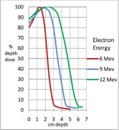
Figure 29.1. Isodose curves for 6-, 9-, and 12-MeV electrons, 8 × 8-cm field, showing greater skin sparing for lower energy electron beams.
Surface and depth doses with both types of beams vary substantially with the spectrum of technical factors (field size, energy, and collimation) selected in tailoring irradiation to the volume requiring treatment. Each new set of factors requires an assessment of dose rate and dose distribution.
With a few exceptions as cited in examples given later, the control rates and the aesthetic and functional results of irradiation of lesions of similar size and location should be similar whether treated with orthovoltage photon beams or electron beams. When differences in outcome have been reported, they sometimes suggest superior control rates with orthovoltage photon beams (3). The most likely explanation for this type of difference relates to the direct transfer of x-ray beam techniques and radiation dose to the use of electron beams in the early days without taking into full consideration of all these differences.
For large fields >8 to 10 cm in diameter, electron beams produce a more homogeneous dose distribution across the surface of the lesion, but decreased dose near the edges must be respected. Also, dose deep to the cancer must be kept to a minimum, such as brain cortex dose when irradiating a cancer of the scalp, where the rapid drop-off in dose at a known depth is a significant advantage of the electron beam. The flexibility and ease of setup, along with the relatively sharp field lateral edges, especially for smaller cancers, are advantages of the x-ray beams. The approximate range of the depth of the 90% isodose line for electron beam energies are shown in Table 29.1. The depth and shape of the isodose lines should be determined for each treatment machine at various energies and field sizes.
Electronic and Radiosotope Brachytherapy
There has been recent interest in using low-energy photons in new electronic and radioisotope brachytherapy devices and techniques. These devices have been initially used in locally irradiating intracavitary locations such as
breast operative sites (7). Their use is expanding to include irradiation of small skin cancers. These devices may be useful in treating small superficial skin cancers that have a diameter of <5 cm and a thickness of <3 or 4 mm. Circular treatment cones are 10, 20, 35, and 50 mm in diameter. The target/source to skin distance is 2 to 3 cm, resulting in a rapid decrease in radiation dose with increasing depth from the cone applicator and skin surface. The percent depth doses for a 50-keV beam at these treatment distances are approximately 58% to 66% at 4 mm depth, and 51% to 60% at 5 mm depth. Some treatment cones use a step filter to provide a flatter isodose curve. There is limited clinical information regarding the efficacy of these devices for treatment of skin cancers at this time.
breast operative sites (7). Their use is expanding to include irradiation of small skin cancers. These devices may be useful in treating small superficial skin cancers that have a diameter of <5 cm and a thickness of <3 or 4 mm. Circular treatment cones are 10, 20, 35, and 50 mm in diameter. The target/source to skin distance is 2 to 3 cm, resulting in a rapid decrease in radiation dose with increasing depth from the cone applicator and skin surface. The percent depth doses for a 50-keV beam at these treatment distances are approximately 58% to 66% at 4 mm depth, and 51% to 60% at 5 mm depth. Some treatment cones use a step filter to provide a flatter isodose curve. There is limited clinical information regarding the efficacy of these devices for treatment of skin cancers at this time.
Field-Defining Devices
When a lead or lead alloy (Cerrobend) cutout is used, the metal must be thick enough to allow transmission of not >5% of the maximum dose (Table 29.2) (8). The following techniques may be used to design the metal cutouts. The outline of the treatment field, which includes consideration of the characteristics of the treatment beam and of occult tumor spread, is marked on the skin with a ballpoint pen or skin-marking ink. This outline is transferred to the surface of the lead as follows:
Overlay the skin surface with a clear plastic sheet that readily conforms to undulations of the surface.
Trace the field outline on the plastic.
Overlay the lead with the plastic. Then with the point of a knife punch the outline through the plastic onto the surface of the lead. Another technique is to draw the field outline on the skin with a ballpoint pen. Overlay clear adhesive tape on the skin. The tape will pick up the ink outline. Place the clear adhesive tape with outline on lead sheet and proceed with the next step.
Table 29.2 Minimum Cerrobend Thickness to Block 95% of Electron Treatment Beam (10 × 10 cm Field Size)
Electron energy (MeV)
Cerrobend thickness (mm)
6
2.3
9
4.4
12
8.5
16
18.0
20
25.0
The thickness of lead required for electron beam blocking is approximately given by (E/2) mm Pb, where E is the incident electron energy; for example, blocking of an 6-MeV electron beam requires lead at least 3-mm thick.
Source: From Purdy JA, Choi MC, Feldman A. Lipowitz metal shielding thickness for dose reduction of 6–20 MeV electrons. Med Phys 1980;7:251–253.
Cut out the lead sheet target field outline with a knife and smooth the edges of the cutout. Rubbing the edge of the cutout with cloth or paper can remove small burrs. Shape the lead to the patient’s contour. Thin lead can be shaped with the fingers. For thicker lead or for shaping to sharply undulating surfaces, such as the medial canthus, the lead can be pressed or hammered lightly to conform to a plaster cast of a face used specifically for this purpose. The hammering must not appreciably thin the lead. Occasionally, it may be necessary to make a plaster cast of the region to shape the lead cutout.
When an electron beam field is defined with a lead cutout placed directly on the skin, the substantial thickness of the cutout requires that it be constructed of multiple layers of thin lead, thick lead cut with a saw, or a shield molded from Cerrobend. With such a surface shield, a zone of increased dose develops just deep into the edge of the cutout (9). The magnitude of this dose increases with beam energy. At lower energies this effect is commonly disregarded. Concern for this effect, the need for bolus, and the ease of block construction encourage the practice of fixing the field-defining device for the electron beam on the end of an electron cone several centimeters from the skin.
When a Cerrobend tailored block is used to define the field of an electron beam, the treatment field outline on the patient is overlaid with a fine metal wire taped in place. The block is constructed from a simulation film or CT scan taken with the patient in the treatment position and with the geometry of the treatment setup in mind. The tailored block is mounted on a cone at a fixed distance from the skin (5–10 cm is common). The thickness of lead required for electron beam blocking is approximately given by (E/2) mm of lead, where E is the incident electron energy in MeV. This means that the field-defining device for electron beams must be substantially thicker than for superficial x-ray beams and that the usual eye shield for an x-ray beam is not adequate for the electron beam commonly used in its place (10,11). For further details of the electron beam’s characteristics and shielding, see Khan (12). When bolus is used, it must be placed on the skin and not placed in an electron cone at some distance from the skin surface (see section on “Bolus”).
Electron Output Correction Factor
It is very important to critically double-check the output factors for small electron fields. Microchambers, thermoluminescent dosimeters (TLDs), or film dosimetry should be used to confirm the proper output factor. Output factors for electron fields smaller than 3 cm in diameter can be erroneous. The output factor for radiation fields of
2 to 3 cm in diameter in our institution is ∼0.90 cGy/MU at 100 source-to-surface distance (SSD). Significant errors in dosage can occur if the output factor is not correct. Output factors that are significantly greater or less than 0.90 should be critically reviewed and double-checked.
2 to 3 cm in diameter in our institution is ∼0.90 cGy/MU at 100 source-to-surface distance (SSD). Significant errors in dosage can occur if the output factor is not correct. Output factors that are significantly greater or less than 0.90 should be critically reviewed and double-checked.
Exit Beam Blocking
Often, normal tissues deep to the treatment volume can be spared by blocking a part or the entire exit beam. The ability to do this varies with anatomic site, extent of cancer, and the patient’s tolerance to the blocking device. Usually with an x-ray beam, a tailored lead shield ∼1 mm thick can be encased in paraffin or dental compound to block, at least, a part of the exit beam and to diminish electron backscatter. When an electron beam exit shield is to be used, some caution is appropriate. Backscatter from the lead can be substantial (30–70% of depth dose at that level). Encasing the shield in dental acrylic or wax of 3 mm thick generally reduces the scatter to an acceptable level for beam energies up to 12 MeV. Finally, the eye shields commonly used with orthovoltage beams are of 2-mm thick lead. This is insufficient for commonly used electron beams, inasmuch as the scatter and transmitted dose can be sufficient to produce cataracts (10,11). In addition, thicker lead eye shields and shields encased in dental acrylic or wax are difficult to insert. For these reasons, x-ray beams are usually preferred for cancers around the eyes.
Bolus
A scattering material such as bolus must be used with 6 and 9 MeV electron beams to ensure that the dose on the skin surface is the maximum tissue dose and to even out irregular contours so as to present a flat surface normal to the electron beam. Superflab (Mick Radio-Nuclear Instruments) is our choice for bolus material, because it is nearly tissue equivalent, transparent, and easy to shape. It is available in 3-, 5-, and 10-mm thickness. This bolus, of course, blurs or masks the outline of the treatment field. For this reason, it is helpful during the treatment setup to align the patient and machine as for irradiation but with a gap to permit bolus placement. The correctness of the position of the treatment field should be visually confirmed. The bolus is then slipped into place. The minimum thickness of bolus to achieve maximum dose at the surface varies with the energy of the electron beam (Table 29.1). Although 5- and 10-mm thick boluses are commonly used for 6- and 9-MeV electrons, based on the percent depth-dose data, an 8-mm thick bolus (combination of 5- and 3-mm thickness) may be more appropriate. When treating to the 90% line, bolus may not be necessary for electron beams of 12 MeV or greater. When it is used, bolus should always be placed on the skin surface. When bolus is located at a distance above the skin, it will cause a scattering of radiation laterally from the designed radiation treatment area.
Related posts:

Stay updated, free articles. Join our Telegram channel

Full access? Get Clinical Tree


