Each preceding chapter has figures, tables, and drawings that aid the author and the editors in imparting and clarifying the messages of the chapter. In this edition of TRAUMA, the editors have devoted a special section to an atlas. It is not intended to include an exhaustive artistic rendering of every operation, but, rather, to focus on procedures that are commonly used in major trauma operations, along with related anatomical drawings. Some procedures that may have been commonly practiced in the past but are rarely currently done are not included. However, a few relatively infrequently used concepts and procedures have been included in this section because of sufficient need to clarify the opinions of the editors. The art has been kept in as simple a form as possible, so it is expeditiously available when needed for a quick refresher in anatomy, anatomical relationships, and/or surgical approach in the “heat of battle.”
FIGURE 4
Steps in Performing a Lateral Parietal Craniectomy
A. The exact location and size of the skin flap vary, depending on extent of the wound but must not extend to the midline at the top of the skull.
B. Skin clips are placed for hemostasis, and burr holes elevate the skull bone flap.
C–D. The bone flap is removed, the dura mater is opened to expose and release an epidural hematoma, and bleeding vessels are ligated. In the absence of significant brain swelling, the skull plate is reattached once hemorrhage is controlled and other necessary procedures have been accomplished. With significant brain swelling, the dura is closed, sometime using dural substitutes, and the bone flap is not replaced at initial operation (decompressive craniotomy).
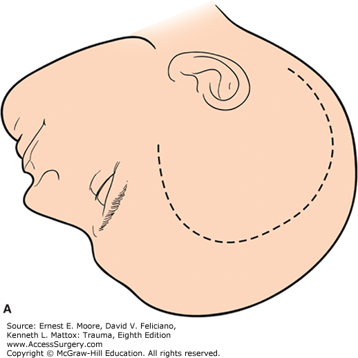
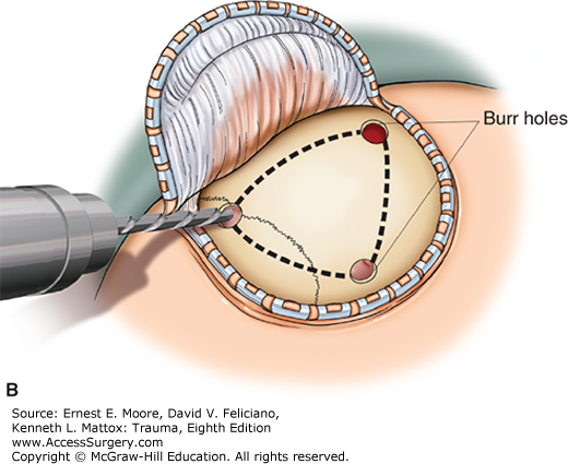
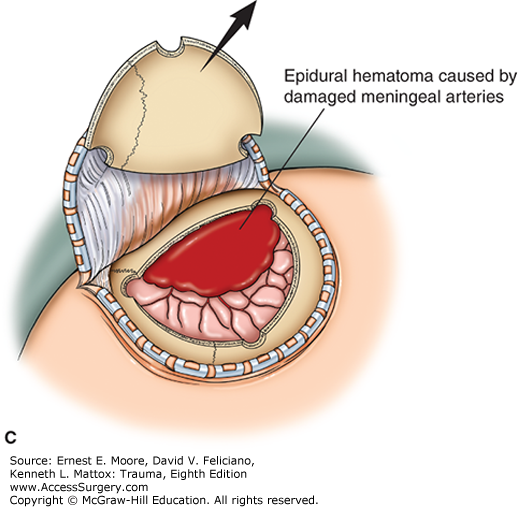
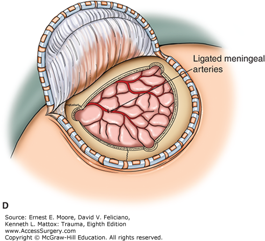
FIGURE 5
Nasal Packing for Hemorrhage Control
A. Under general or topical anesthesia, gauze impregnated with Vaseline to facilitate insertion is layered into a bleeding nasal passage to achieve hemostasis.
B. Balloon devices are commercially available to provide posterior and anterior nasal packing.
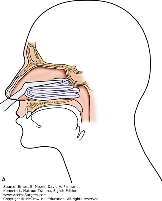
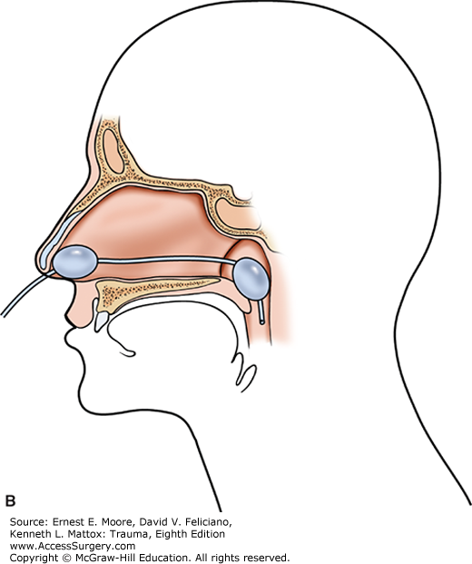
FIGURE 7
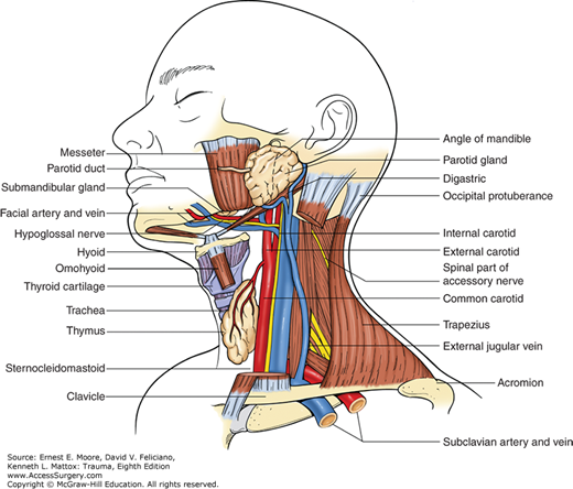
Anatomy of the Neck
Anterior Perspective—Although usually approached from incisions just anterior to the sternocleidomastoid muscle, the surgeon must always review the cervical anatomy and its structural relationships prior to incision. The external jugular vein is a subcutaneous structure, and the internal jugular vein and carotid arteries are deep and medial in the neck.
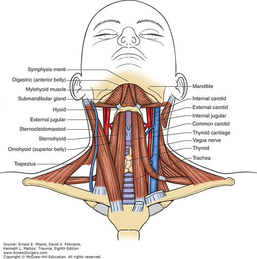
FIGURE 9
Carotid Artery
There are six branches of the external carotid artery. The right carotid artery is the mirror image of the left. Note that the internal carotid artery has no extracranial branches and is always lateral to the external carotid artery. The height of the bifurcation of the common carotid artery in the neck is variable. The facial vein, which can be divided between clamps with impunity, is not shown in this drawing. This division of the facial vein opens the deep anatomy of the mid lateral neck in the area of the bifurcation of the common carotid artery.
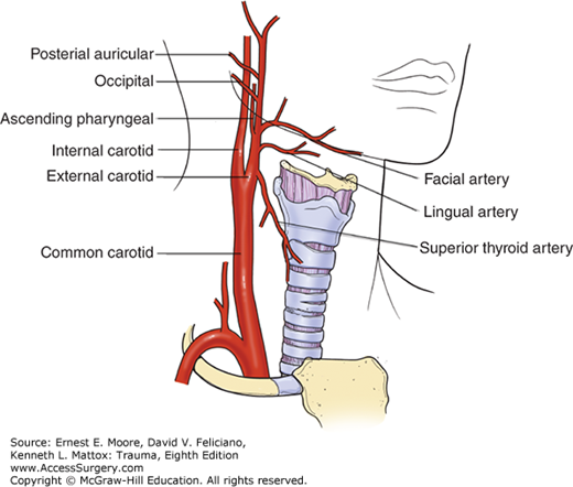
FIGURE 10
Repair Techniques for Injury to the Common Carotid Artery Proximal to the Bifurcation
A. The injured vessel is debrided after proximal and distal control is obtained. Local heparinized saline is injected distally.
B. If the injury is not extensive, end-to-end anastomosis with 5 (0) polypropylene running suture using a “parachuting” technique is possible. Note, with adequate arterial collateral circulation, a temporary carotid artery shunt is not required.
C. If the artery is going to be under tension or stretched, an interposition graft of Dacron (shown), polytetrafluoroethylene (PTFE), or scavenged vein is inserted.
Prior to completely releasing the clamps and before prograde flow is reestablished to the brain, any microclots that might have formed during the procedure are adequately flushed out, both proximally and distally.
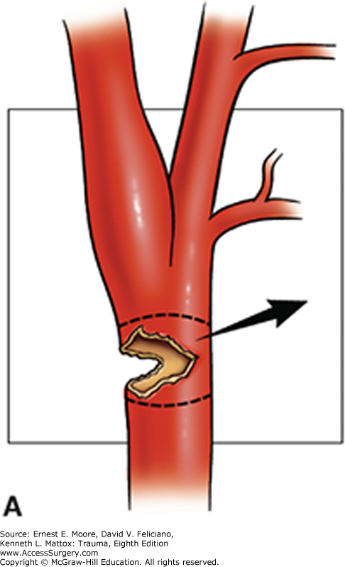
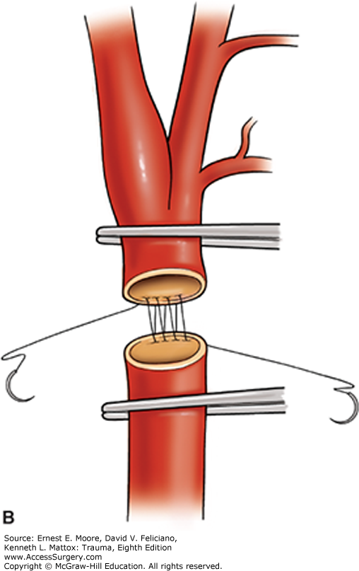
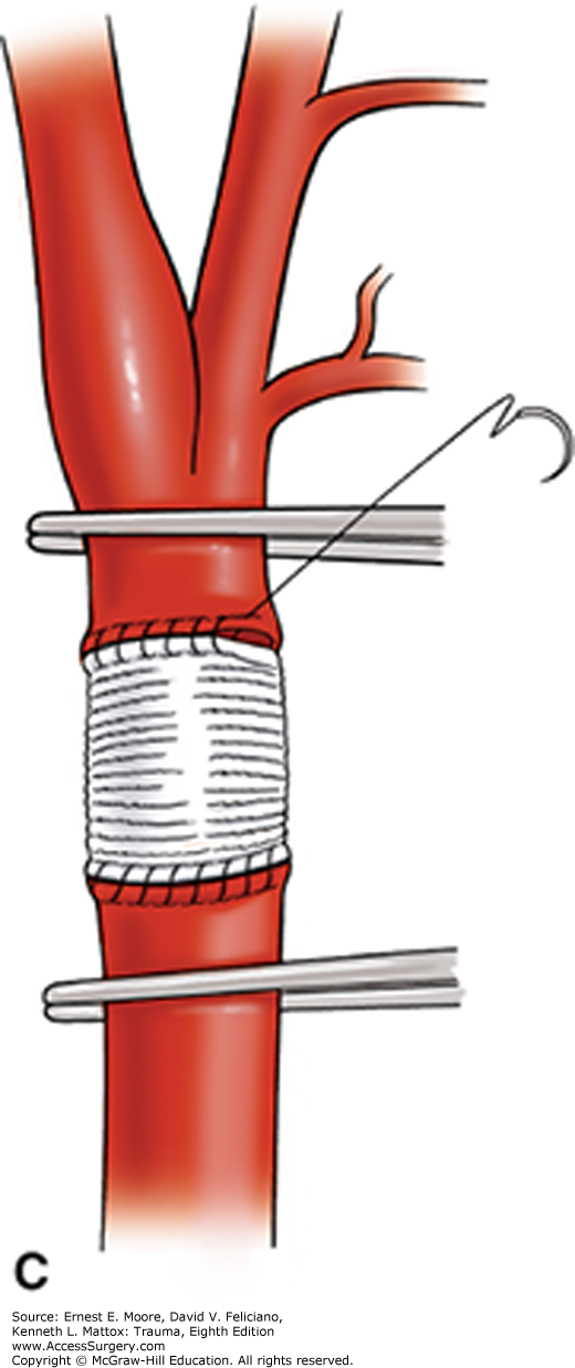
FIGURE 11
Alternative Approach to Interposition Grafting for an Injury to the Proximal Internal Carotid Artery
A. Following proximal and distal control and instillation of local heparinized saline, the area of injury is resected, and the external carotid artery is mobilized for a distance sufficient to bridge the gap for the injured internal carotid artery.
B. The origin of the proximal internal carotid artery is oversewn, and one anastomosis is accomplished using the mobilized external carotid artery branch to beyond the injury on the internal carotid artery. Ligation of one or two branches of the external carotid artery may be required to accomplish significant mobilization.
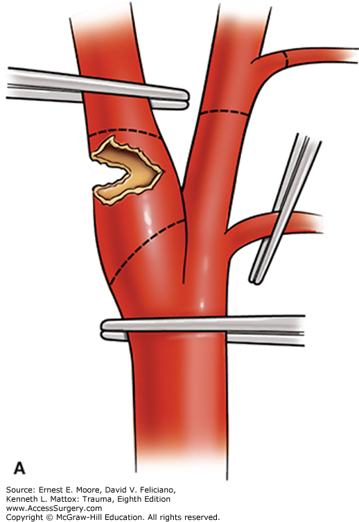
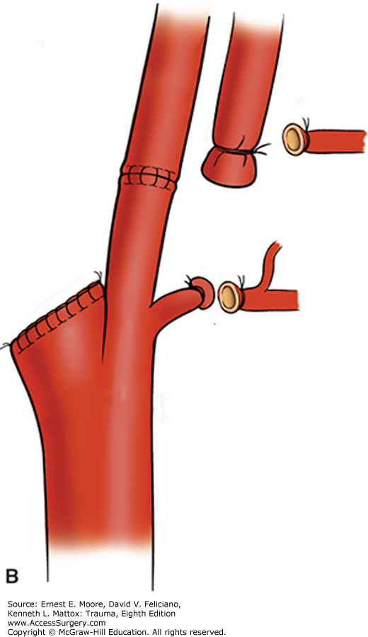
FIGURE 12
Repair of a Combined Injury to the Trachea and Esophagus
A. Following repair using interrupted absorbable sutures on the trachea, a vascularized muscle pedicle (such as the sternal head of the sternocleidomastoid muscle) is interposed between these two tubular structures to reduce the postrepair complication of fistula formation.
B. The procedure demonstrated in cross section.
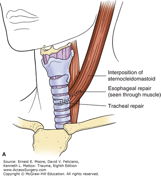
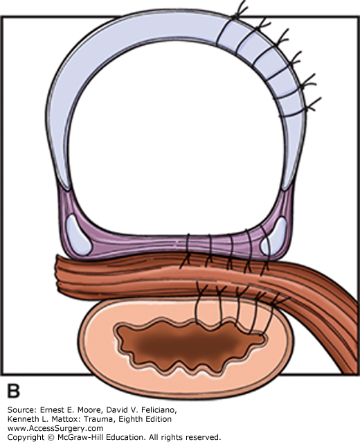
FIGURE 13
Vertebral Artery
This demonstrates the bilateral vertebral arteries arising as the first branch off the corresponding subclavian artery in the neck, entering the transverse foramen of the sixth cervical vertebra, and exiting the transverse foramen of the second cervical vertebra, to join the opposite vertebral artery to form the basilar artery. Note that all portions of the vertebral arteries are anterior to the cervical nerves.
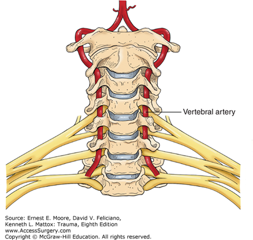
FIGURE 14
Control of Injured Vertebral Artery
A. The vertebral artery lies deep in the neck inside the transverse foramen of the cervical vertebra. For uncontrolled bleeding from an injured vertebral artery within the transverse foramen of the neck, dissection and unroofing of this bony covering can be difficult and even produce additional injury and complications.
B. Bone wax pressed into the area of bleeding can rapidly control persistent bleeding.
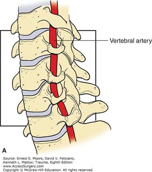
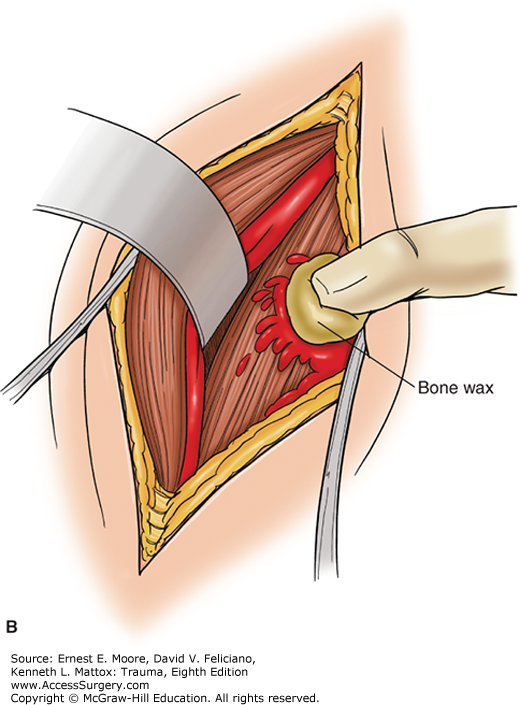
FIGURE 15
Percutaneous Tracheostomy
A. This drawing depicts the initial approach to a percutaneous tracheostomy. The trachea, location of the larynx, and the first few tracheal rings are palpated. The initial needle insertion site is between the first and second tracheal rings.
B. This is a lateral view of the dilation maneuver of the trachea as part of a percutaneous tracheostomy. A needle has been inserted between the first and the second tracheal rings, with a wire inserted through the needle. A dilating device is inserted over this wire into the trachea, and a tracheostomy tube is inserted into this stoma. During the insertion of the initial needle, care is taken to avoid perforation of the occluding balloon on the endotracheal tube.
C. This is a lateral view of a completed percutaneous tracheostomy. Note that a tracheostomy tube has been inserted through the orifice created by the dilator inserted between the first and second tracheal rings. The endotracheal tube inserted via the mouth has been removed.
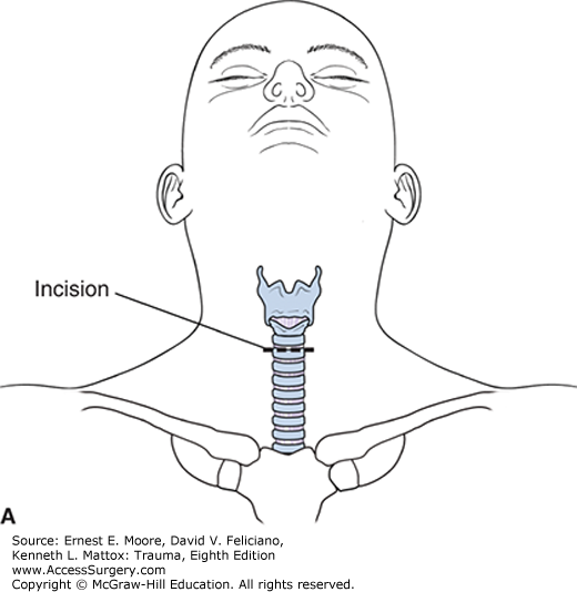
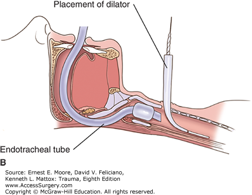
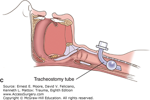
FIGURE 16
Alternate Neck Incisions
A. For thoracic outlet injuries (Zone 1 cervical injuries), median sternotomy may be combined with either a right or left classic anterior neck incision, which allows for proximal vascular control.
B. For injury to the proximal extrathoracic subclavian artery, supraclavicular extension of a median sternotomy allows for proximal control as well as exposure, should division or removal of the clavicle be required for exposure and repair of the injury.
In some instances, such as an injury to the proximal left carotid artery, it is necessary to extend the median sternotomy into an anterior neck incision.
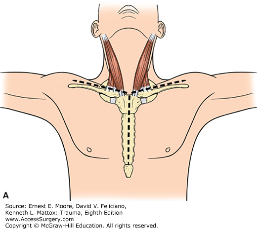
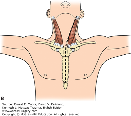
FIGURE 17
Median Sternotomy With a Neck Extension for Access to the Left Proximal Common Carotid Artery Injury
A neck incision or a median sternotomy, alone, is insufficient for control and reconstruction of injury to the left proximal common carotid artery. However, a combined incision, aided by two retractors, affords excellent exposure. The hematoma is often extensive. Note the location of the left vagus nerve, with its recurrent laryngeal nerve, around the aortic arch. Also note the lateral location of the left phrenic nerve. Concomitant venous injury and bleeding is common.
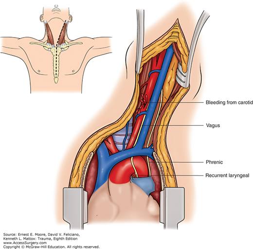
FIGURE 18
Subclavian Artery Anatomy
This illustrates the cervical anatomy of the subclavian arteries, with arms at the patient’s sides, which places the clavicles at their lowest positions. The arms in the outward, extended positions result in clavicles covering the subclavian arteries. Note that both the right and left subclavian arteries have four branches.
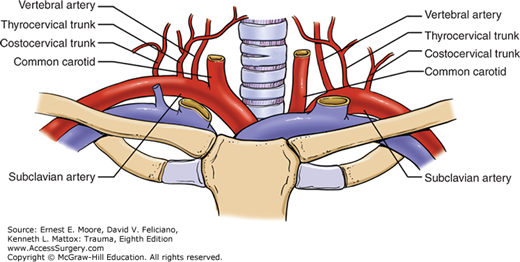
FIGURE 19
Anatomy of the Thoracic Duct
At the base of the mesentery, anterior to the abdominal aorta and very near the left renal vein, the cisterna chyli collects lymph from the mesenteric lymphatic channels and carries lymph upward, continuing anterior to the thoracic aorta on to the thoracic outlet, via the lymphatic duct. Other numerous lymphatic collateral channels join this thoracic lymphatic duct, where it bifurcates in the upper posterior chest. Although the left thoracic duct is the larger, a thoracic duct empties into the right superior subclavian vein just as it receives the corresponding internal jugular vein. Note that the thoracic duct is anterior to the subclavian artery and posterior to the subclavian vein.
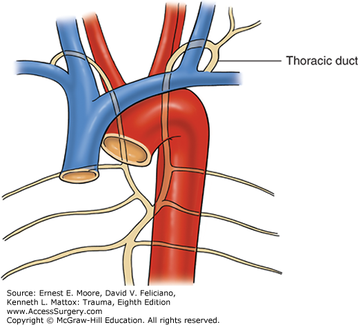
FIGURE 20
Controlling Hemorrhage From the Subclavian Artery
A. Temporary vascular control is achieved via short anterior third interspace incision with a vascular clamp applied to the intrathoracic left subclavian artery.
B. Alternately, control can be achieved using a Rommel tourniquet.
Note: In the emergency room, this injury can be immediately temporarily controlled with the tamponading finger or an inflated 30 mL Foley balloon.
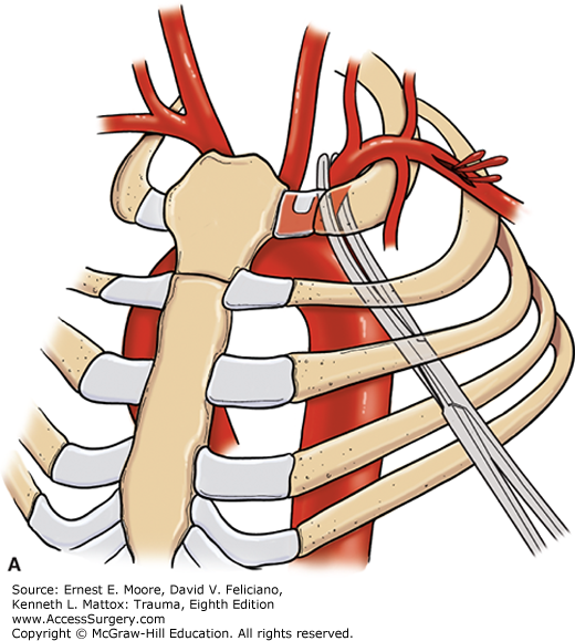
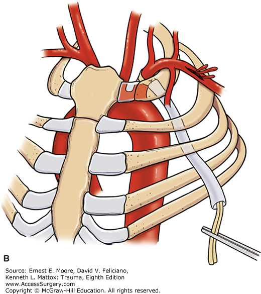
FIGURE 21
Exposure and Repair of a Subclavian Artery Injury
A. Although endovascular stent graft options are increasingly being used for injury to the subclavian artery, they are not always available, so direct exposure may be required. With the arm prepped free but positioned at the patient’s side, clavicular division or resection might aid in exposure. A liberal supraclavicular incision is made over the clavicle.
B. The bone is exposed using a periosteal elevator.
C. The clavicle is divided in its middle portion, and the proximal end may be retracted medially.
D. The key to the fossa containing the subclavian artery is to remove the scalene fat pad. The phrenic nerve resides in the middle one-third of the scalene anticus muscle, the lateral half body of which is divided to aid exposure.
E. The subclavian artery is extremely fragile, and a saphenous vein is the preferred conduit to use in an open reconstruction.
F. Following vascular reconstruction, the clavicle can be reconstructed with orthopedic plating.
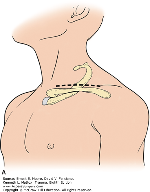
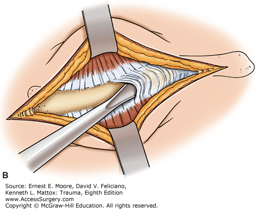
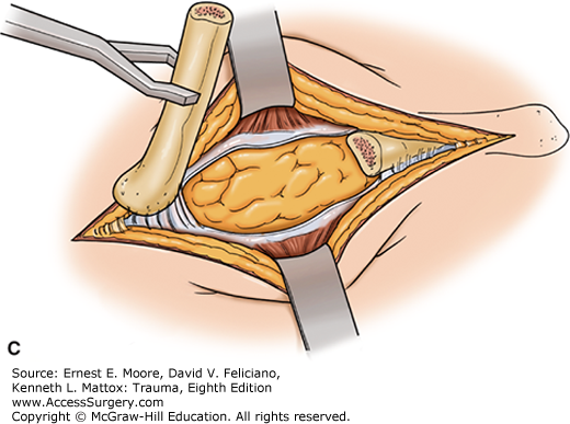
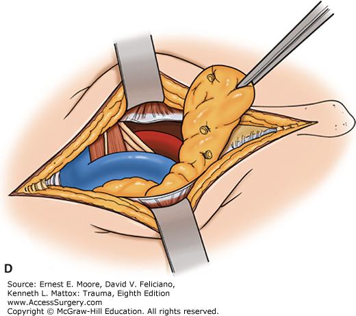
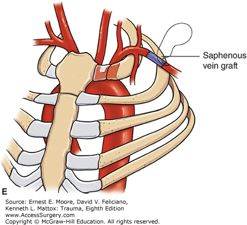
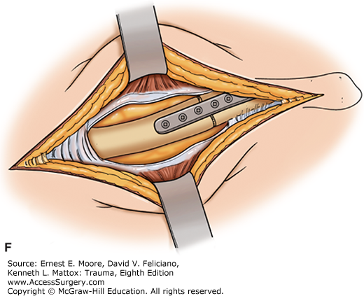
FIGURE 22
Tube Thoracostomy, the Most Commonly Performed Thoracic (Operative) Procedure
A. The lateral anatomy in the auscultatory triangle at the fourth intercostal space in the midclavicular line is the point for chest tube insertion.
B. Following adequate anesthesia, skin incision, and dissection of subcutaneous tissue are accomplished, and a large clamp or dissecting scissors are used to spread the intercostal muscles. The pleura is entered with the probing finger. Up to 25% of patients have some element of pleural symphysis, and entering the pleura with a Trocar or other similar instrument risks producing an iatrogenic lung injury. The finger allows digital exploration to discern the pericardium or a diaphragmatic injury and/or release pleural adhesions.
C. After an appropriately sized hole is created, a chest tube is introduced with the aid of a large curved clamp attached to the tip and directing the tube to the posterior apex location of the pleural space. The tube is attached to an appropriate collection, water seal, and negative pressure device.
D. The chest tube is aimed toward the apex of the pleura, with the last hole in the tube inside the chest wall.
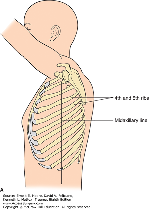
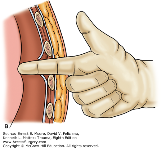
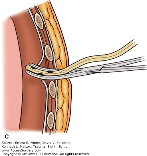
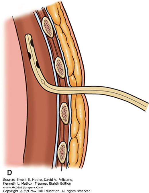
FIGURE 23
Resuscitative Thoracotomy 1
This depicts the standard left anterolateral thoracotomy. The dotted line depicts the incision for a left anterolateral thoracotomy into a bilateral anterolateral (clam shell) thoracotomy. Note that the left incision is in the area of the fourth or fifth interspace, and below the mammary crease.
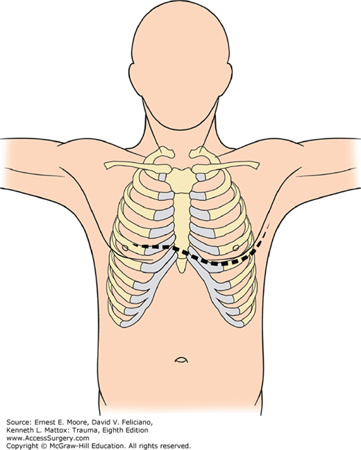
FIGURE 24
Resuscitative Thoracotomy 2
This is the anterior mediastinum and both anterior thoraces following bilateral anterolateral or clamshell thoracotomy. Note that one can visualize both lungs, the pericardium, the heart, and all of its chambers, the superior and inferior vena cava, the ascending aorta, the pulmonary artery, the innominate vein, the innominate artery, and the right and left carotid arteries. This drawing does not show, but assumes the ligation of both divided ends of the right and left internal thoracic (mammary) arteries.
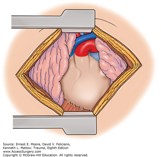
FIGURE 25
Cross-clamping of the Thoracic Aorta
A. With the patient in the supine position, a left fourth or fifth interspace curvilinear incision is made beneath the nipple and breast fold aiming to the axilla. The aorta is clamped higher in the chest, at the proximal descending thoracic aorta, using a vascular clamp.
B. Alternately, the aorta may be cross-clamped low in the chest. The lung pushed upward, showing the heart within the pericardium, the phrenic nerve, the diaphragm, and the aorta. The esophagus is seen anterior to the aorta and the spine, with the segmental arteries coming off at each interspace. The aorta is cross-clamped low in the thorax using a vascular clamp.
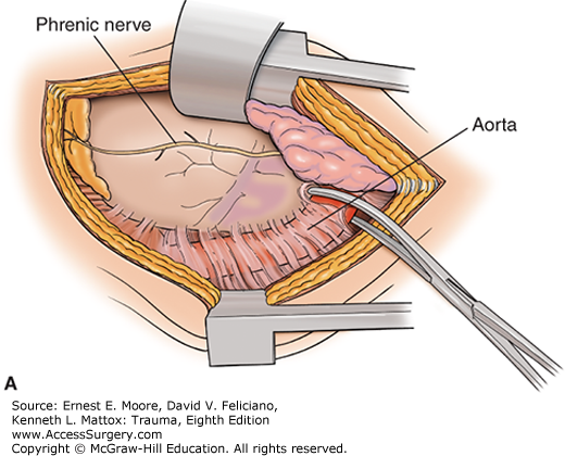
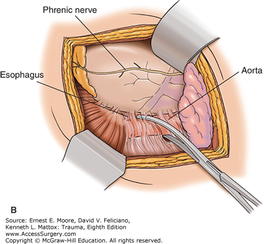
FIGURE 26
Opening the Pericardium to Explore the Heart
Using scissors or a scalpel, the left pericardium is incised, with the lung positioned posteriorly. The incision is made anterior and parallel to the phrenic nerve. With a tense hemopericardium, purchase of the pericardium is difficult, making this maneuver challenging. The ratchet mechanism of the chest wall retractor is positioned posteriorly.
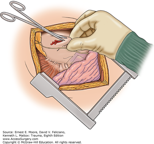
FIGURE 27
REBOA
An alternative for resuscitative thoracotomy for no thoracic injuries is the REBOA. The REBOA is an occluding balloon introduced via the common femoral artery, which is typically entered percutaneously but occasionally direct cut down is used. In this instance, the balloon has been inflated distal to the renal arteries (Zone III). Several different versions, sizes, and varieties of endovascular occluding balloons exist.
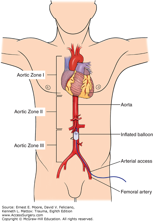
FIGURE 28
Thoracic Incision Options
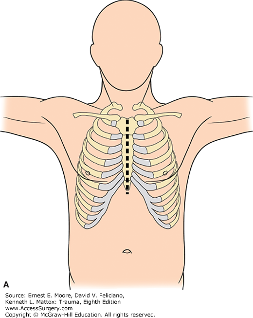
A. The median sternotomy is the standard incision for anterior cardiac and thoracic outlet vascular injury, but is not an appropriate incision for approach to posterior mediastinal structures or the pulmonary hilum.
B. A median sternotomy with an anterior neck or supraclavicular extension is used for thoracic outlet great vessel injuries to Zone 1 of the neck.
C. The anterolateral incision, particularly on the left, is the utility emergency thoracotomy for trauma and resuscitation. It is made from the sternal edge, under the mammary fold, and in a curvilinear fashion toward the axilla, staying in close proximity to the fourth or fifth intercostal space. This incision should not be a straight line incision nor be carried through the female breast.
D. Bilateral anterolateral incisions may be either separate or combined and transternal. When transternal, the sternum is traversed with a Gigli saw or other cutting device, and the internal thoracic arteries are ligated on both sides on the upper and lower incision sites (four ligatures). Both incisions should be curvilinear, with the transternal cut high enough on the sternum to expose the mid-portion of the heart and also with sufficient sternum to accomplish a solid bony closure. On occasion, when a right-sided injury is suspected high in the pleural cavity, the incision might even be above the right nipple.
E. In the female, the anterolateral incision is at the inframammary fold and is accomplished by moving the breast tissue cranially.
F. With the patient in a lateral decubitus position, a posterolateral fourth or fifth interspace incision can be made from near the area of the nipple, laterally around to near the spinal canal. This incision for trauma traverses the latissimus dorsi muscle and portions of other chest muscles. The scapula must be retracted superiorly to achieve fourth or fifth interspace incisions. This incision provides exposure of posterior mediastinal structures, such as the aorta, lung hilum, esophagus, trachea, and azygos vein.
Stay updated, free articles. Join our Telegram channel

Full access? Get Clinical Tree


